Alpha Technologies XM3-HP Series - Technical Manual User Manual
Page 24
24
017-882-B0-001 Rev. C2 (10/2013)
1.0
Introduction
1.3
Alpha XM3-HP CableUPS Layout, continued
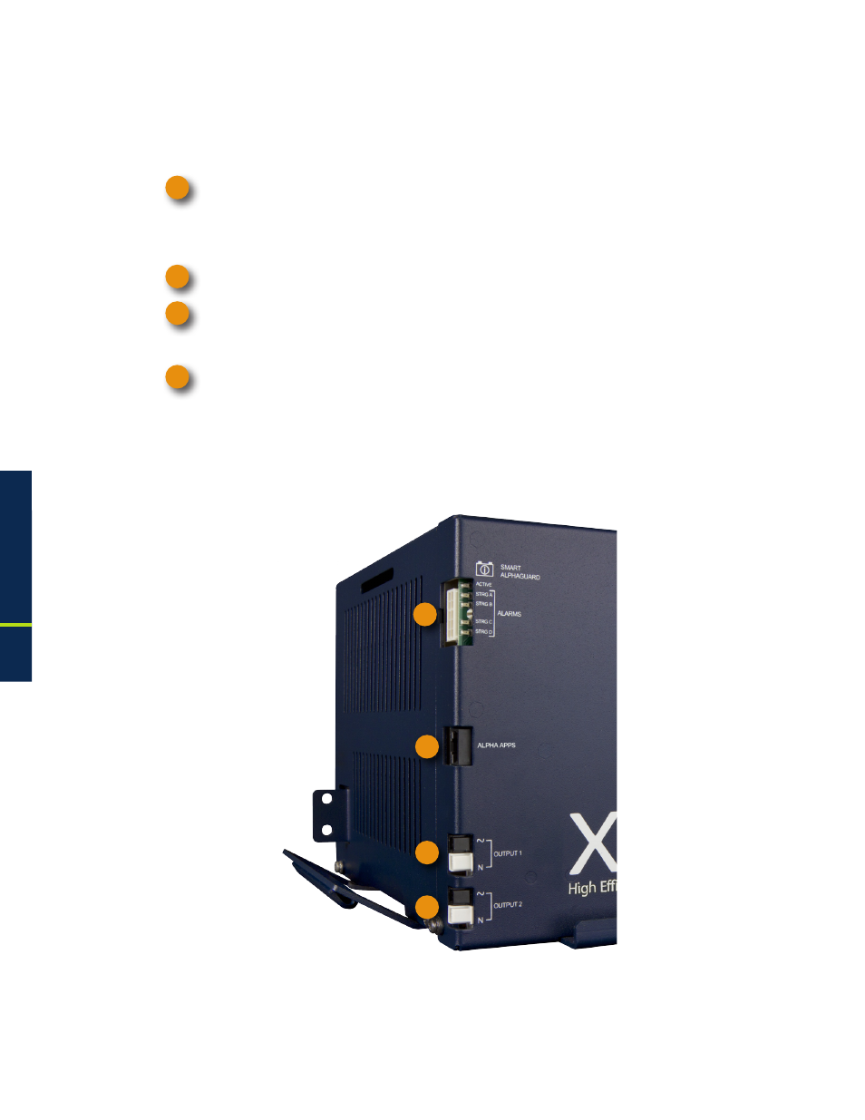
1.3.2 Front Panel Indicators
Circuit boards for the optional Smart AlphaGuard (SAG), Alpha APPS card and the two-output
AlphaDOC (PIM) are located behind the removable front panel.
Smart AlphaGuard (SAG): Enables the XM3 to gather battery voltage data for up four battery
strings (A through D). Its Charge Management Technology applies excess charge current to
batteries as needed to maintain balanced voltages throughout the string. See
Section 1.3.4,
Smart AlphaGuard for connection information and LED functionality.
Alpha APPS Card
Output 1 (White = Neutral, Black = Line): The AC output connector is clearly marked and color-
coded for easy identification. The Service Power Inserter (SPI) connects directly into the Output 1
connector.
Output 2 (White = Neutral, Black = Line): When no AlphaDOC is installed, this output is wired in
parallel to Output 1 and is often used for auxiliary loads. If the AlphaDOC is installed, Output 2
can be isolated from Output 1.
Fig. 1-7, Detail View, Front Panel Connections and
Indicators
1
2
3
4
1
2
3
4
1.0
Introduction, continued