Alpha Technologies XM3-HP Series - Technical Manual User Manual
Page 46
46
017-882-B0-001 Rev. C2 (10/2013)
2.0
Installation
2.2
XM3-HP Start-Up Procedure, continued
2.2.7 Communications DOCSIS Status Monitoring, continued
2.0
Installation, continued
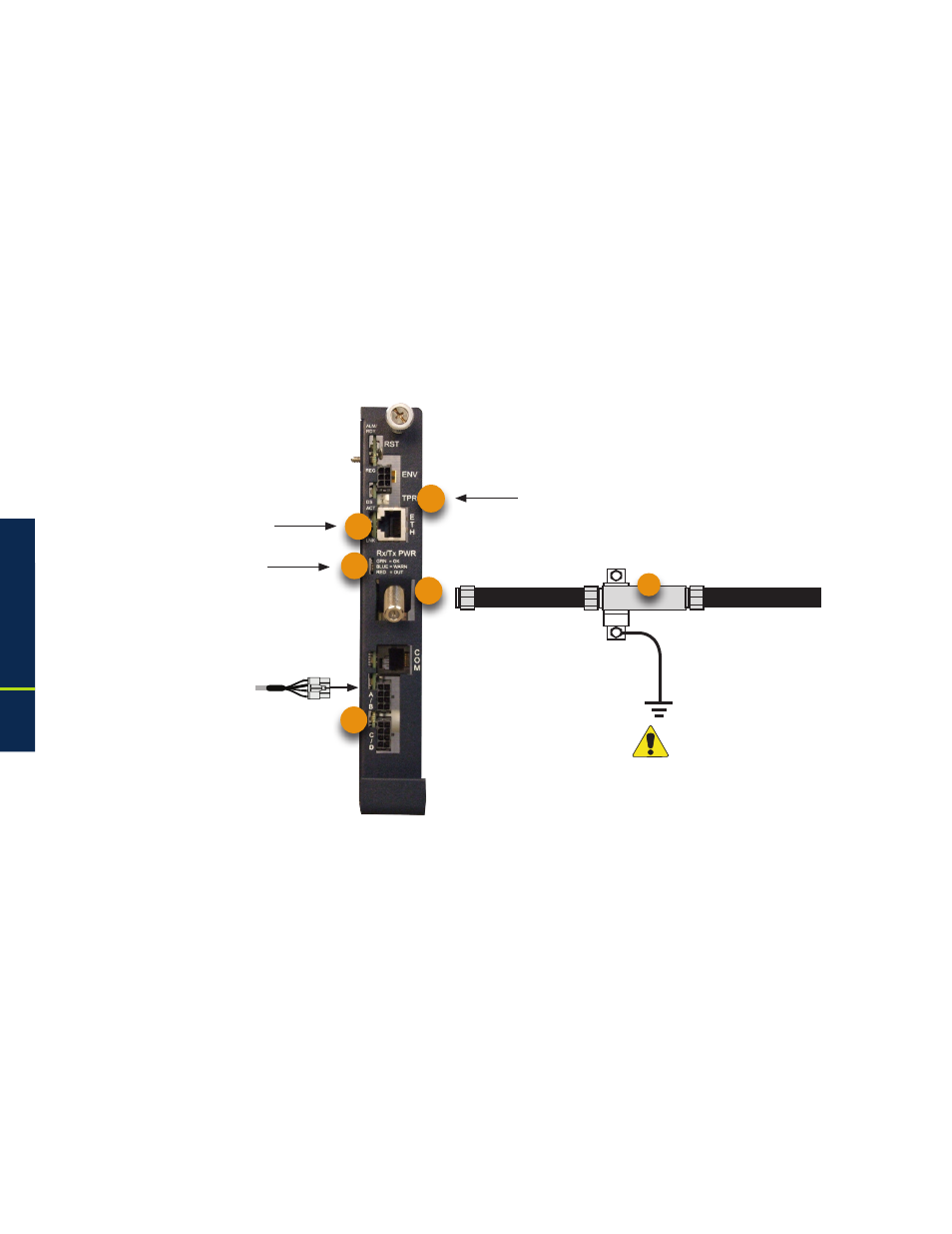
1. Connect Battery Sense Wire Harness to the A/B, C/D connection points (14) on the
transponder. The connection (14) is not required for individual battery monitoring if
the Smart AlphaGuard option is deployed. For XM3 units with the Smart AlphaGuard
option, connect the Battery Harness (5) to the AlphaGuard connection located on the
left side of the XM3 Power Supply.
2. Connect Tamper Switch Wire Harness to the TPR Connector (18).
3. Connect the RF drop (15) and make front panel connections as shown below for
the DSM3. The DOCSIS specification for downstream power level is +/-15 dBmV.
However, for optimal performance, set the level as close to 0 dBmV as possible.
2.2.7.1 DOCSIS Status Monitor Front Panel Connections
To Battery Sense Wire
Harnesses
Tamper Switch Connector
Required
Grounded Surge Protector
(Alpha p/n 162-028-10 or equivalent)
14
15
18
RF Cable to Headend
20
19
Green/Blue/Red
LED Indicators
Ethernet Connector
Fig. 2-23, DOCSIS Status Monitor Front Panel Connections
9