0 operation 3.5 active alarms – Alpha Technologies XM3-HP Series - Technical Manual User Manual
Page 80
80
017-882-B0-001 Rev. C2 (10/2013)
3.0
Operation
3.5 Active Alarms
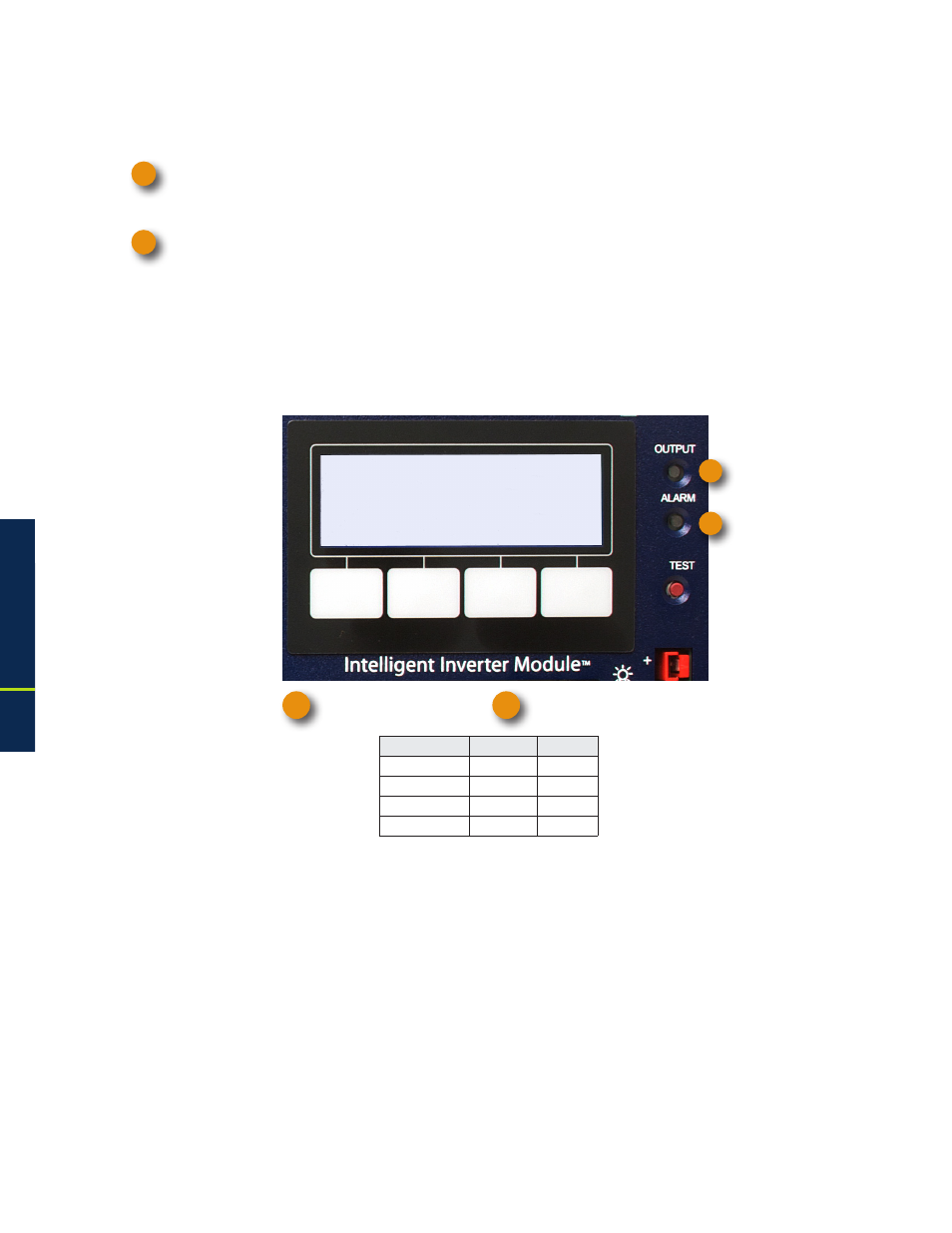
Two LEDs on the Inverter Module indicate the condition and status of the Intelligent CableUPS.
The green Output LED, when lit, indicates the Power Supply is functioning normally and supplying output
AC to the load. A flashing output LED indicates that an alarm has been detected. If the Output LED is off, the
output is off.
The red Alarm LED flashes to indicate a major alarm has been detected. This state clears when the alarm is
no longer present. Under typical operating situations, the red Alarm LED is off. This indicates normal Power
Supply operation.
In the event of a failure, the Active Alarm displays which alarms are active and how to correct the alarm condition.
• Press the menu key with ALM indicated above it to see the ACTIVE ALARM list for the selected key.
• Press UP or DOWN to select the alarm of interest.
• Press ENTR to select the alarm and display diagnostic information. Press ESC to return to the alarm list.
A Help sub-menu provides possible remedies relating to the active alarm. To access the Active Alarm Help
sub-menu, scroll to the alarm of interest and press ENTR. Press either UP or DOWN to scroll through the list
of remedies.
Alarms are classified in two categories:
MAJOR Alarms are indications of a serious failure within the Power Supply, such as a loss of output voltage or a
failed battery charger. Any situation that causes output failure is considered a Major Alarm. Major Alarms require
immediate action to correct the failure. To correct Major Alarms, follow the Smart Display on-screen instructions.
MINOR Alarms indicate a less serious failure, such as defective PTS or loss of utility power. Corrective action
can be delayed for a short time. To correct, follow the Smart Display on-screen instructions.
The alarm matrices on the following pages indicate the MAJOR/MINOR active alarms, the probable cause,
troubleshooting items to check to correct the alarm condition, and whether or not Standby is disabled for that
alarm type.
Fig. 3-3, Active Alarm Table
(Alarm Conditions exist in the Battery and Communications subsystems)
XM3-918HP
90V/0.4A
**ACTIVE ALARM**
OK
PWR
PM
BATT
ALM
COMM
OK
APPS
1
2
OUTPUT LED (green)
1
2
ALARM LED (red)
Condition
Output Alarm
Normal
On
Off
Minor
Flash
Off
Major
Flash
Flash
Output Off
Off
Flash
3.0
Operation, continued
1
2