0 installation – Alpha Technologies XM3-HP Series - Technical Manual User Manual
Page 47
47
017-882-B0-001 Rev. C2 (10/2013)
2.0
Installation
2.2
XM3-HP Start-Up Procedure, continued
2.2.7 Communications DOCSIS Status Monitoring, continued
2.0
Installation, continued
Verify the DSM3 LEDs behavior is as follows:
Refer to Step 4 in the above table for normal LED behavior when the DSM3 is fully functional.
• Blue Rx/Tx Power LED indicates Rx/Tx Power at a warning level. Make the necessary RF level
adjustments.
• Red Rx/Tx Power LED indicates Rx/Tx Power at an alert level. Make the necessary RF level
adjustments.
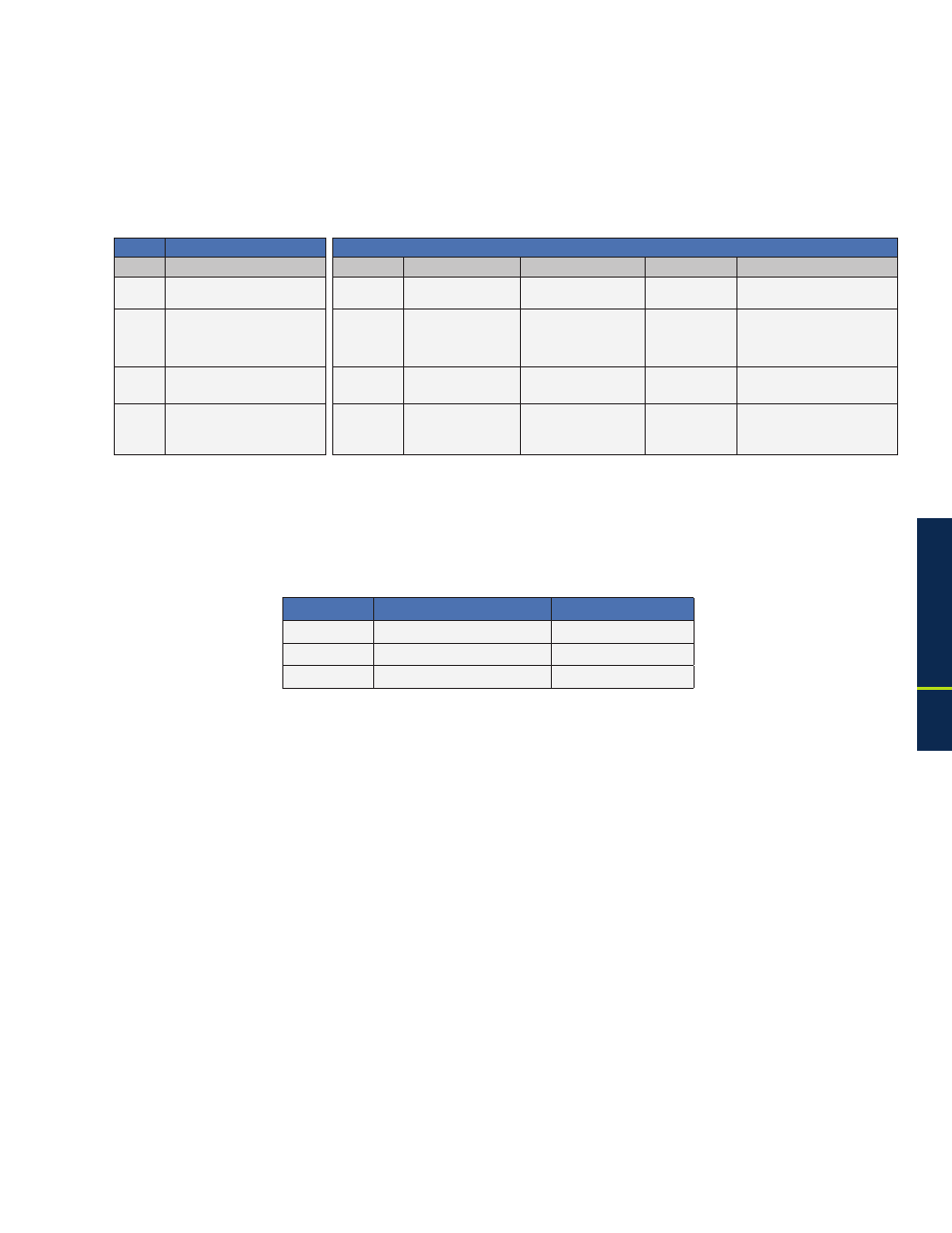
LEDs and Indications (20)
Step
Communications State
ALM/RDY Downstream (DS) Registration (REG) Rx/Tx Power
Communications (COM)
1
Transponder Initializing/Searching
for Downstream DOCSIS channel
Flashing
(Green)
Flashing
OFF
OFF
Flashing
2
DOCSIS Channel locked -
Completing upstream and network
registration
Flashing
(Green)
ON
Flashing
ON (Green)
Flashing
3
Online - Registration Complete
Flashing
(Green)
ON
ON
ON (Green)
Flashing
4
DSM3 Series fully functional
Flashing
(Green)
ON
ON
ON (Green)
Bursts when Communicating
LED Color
Rx Range (dBmV)
Tx Range (dBmV)
Green
+10 to -10
0 to +50
Blue
+15 to +10 and -10 to -15
+50 to +55
Red
>+15 and <-15
>+55
2.2.7.2 LED Status Verification
Table 2-1, DSM3 LEDs Behavior