0 installation, Alm/ rdy, Reg ds act lnk blue = warn red = out grn = ok – Alpha Technologies XM3-HP Series - Technical Manual User Manual
Page 45: Input failure n+1 in use
45
017-882-B0-001 Rev. C2 (10/2013)
2.0
Installation
2.0
Installation, continued
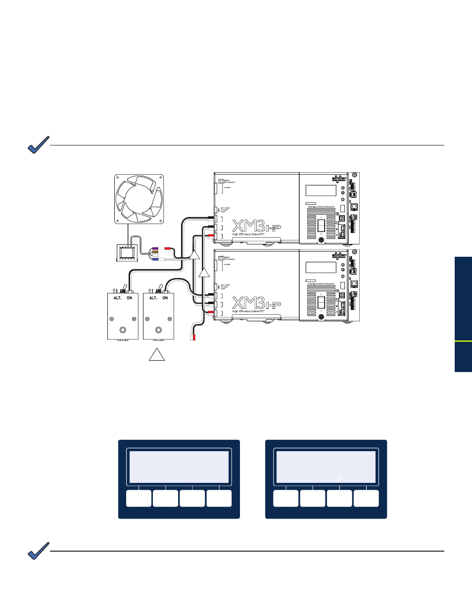
2.2.6 Optional N+1 Configurations, continued
The N+1 ports are used in redundant system configurations where multiple power supplies are housed
in a single enclosure. In the event of a power supply failure, a redundant power supply (with an optional
DOC with N+1 board installed) is automatically switched into service with approximately a 8ms delay. This
feature is part of the DOC with N+1 option.
This provision also protects system components by shutting down the load during overcurrent and short
circuit conditions. Adding a DOC with N+1 in the secondary power supply enables both power supplies to be
connected in a “dual redundant” configuration so the system can protect two critical loads (see Fig. 2-20).
The N+1 unit and the primary unit cannot be loaded over 50% of rated capacity when configured as shown below.
NOTE:
75V
60V
SPI #1
SPI #1
SPI #1
~
N
ALM/
RDY
RST
FLASH = MIN ALM
~
N
SOLID = MAJ ALM
STRG A
STRG B
STRG C
STRG D
TPR
Rx/Tx PWR
E
T
H
A
/
B
C
/
D
C
O
M
REG
DS
ACT
LNK
BLUE = WARN
RED = OUT
GRN = OK
ON
OFF
O
I
i
~
N
OUTPUT
ALARM
TEST
BATTERY
TEMP
LRI
BATTERY
INPUT
BATTERY
BREAKER
N + 1
~
N
ALM/
RDY
RST
FLASH = MIN ALM
OUTPUT 1
~
N
OUTPUT 2
SOLID = MAJ ALM
STRG A
STRG B
STRG C
STRG D
TPR
Rx/Tx PWR
E
T
H
A
/
B
C
/
D
C
O
M
REG
DS
ACT
LNK
BLUE = WARN
RED = OUT
GRN = OK
ON
OFF
O
I
i
~
N
OUTPUT
ALARM
TEST
BATTERY
TEMP
LRI
BATTERY
INPUT
BATTERY
BREAKER
N + 1
OUTPUT 1
OUTPUT 2
SPI #2
1
1
90V
Fig. 2-20, Dual Redundancy N+1 Configuration
1 Wire Kit (Alpha P/N: 875-994-20)
When the power supply is in N+1 operation, the active alarm menu screen will display (see Figure 2-21).
Additionally, the Output Voltage and Output Current display in the upper right hand corner of the Smart
Display will show 0 Volts and a value for the Output Current Amperage (e.g. 0V/10.8A). This Output
Current Amperage is the sum of output terminals. By pressing the softkey below the PWR menu the
Active Alarms menu will display (see Figure 2-22).
INPUT FAILURE
N+1 IN USE
**
ACTIVE ALARMS **
ESC
XM3
0V/10.8A
**
ACTIVE ALARMS **
ALM
OK
OK
OK
PWR BATT COMM APPS
Fig. 2-21, Active Alarm Screen
Fig. 2-22, N+1 In Use Alarm Screen
When N+1 is in use, the displayed Output Current will not agree with the Output Current CIB on the remote status
monitoring web-page, which will show 0 Volts for Output Voltage and 0 Amps for the Output Current. However, the
Output Current displayed on the Smart Display will be correct for the output terminals.
NOTE: