Alpha Technologies XM3-HP Series - Technical Manual User Manual
Page 34
34
017-882-B0-001 Rev. C2 (10/2013)
1.0
Introduction
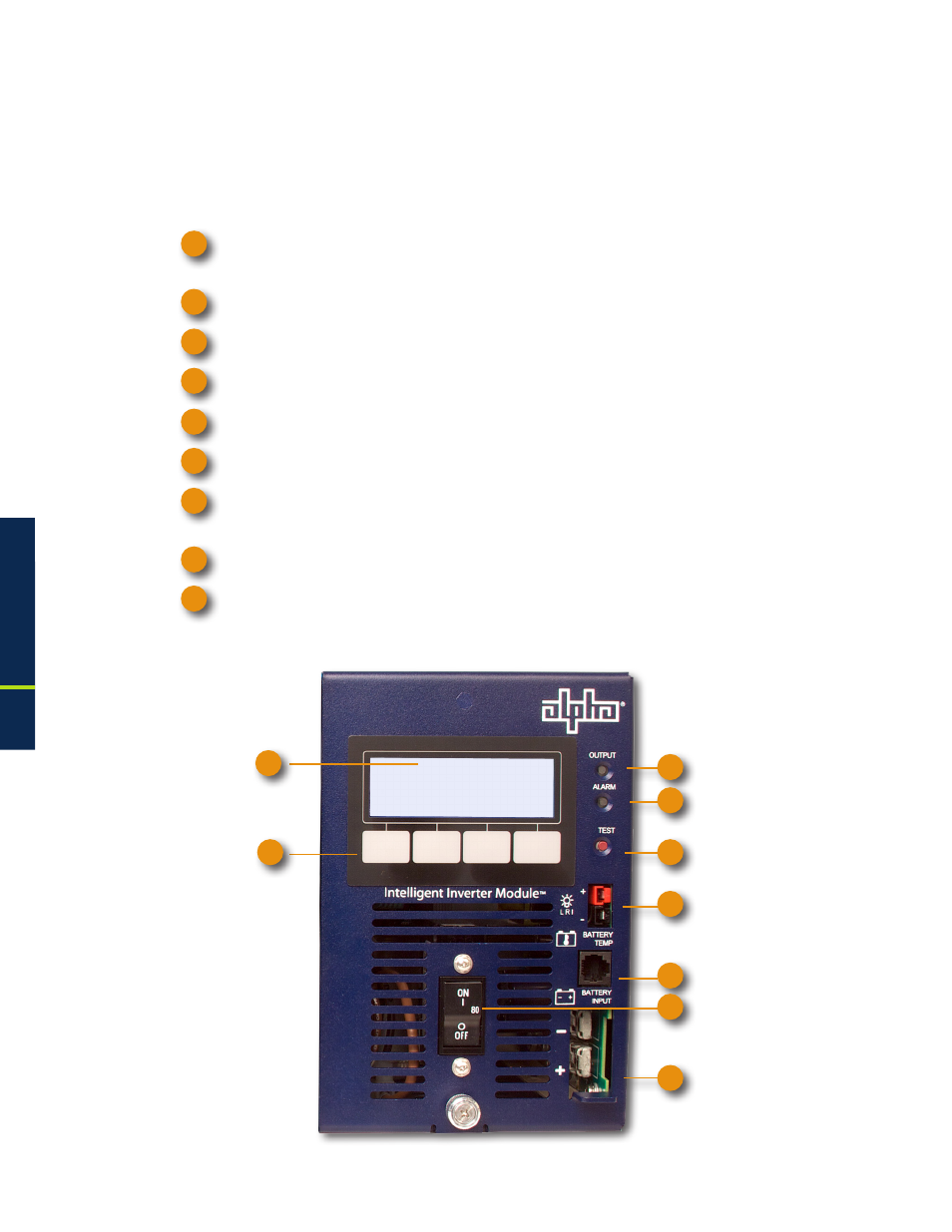
Fig. 1-14, Inverter Module Connections
1.3
Alpha XM3-HP CableUPS Layout, continued
1.3.5 Inverter Module Overview
The removable Inverter Module provides uninterrupted power to the ferroresonant transformer
(via the batteries) during utility failures. During normal operation, the inverter charges the
batteries using a three-, four- or five-stage (Bulk, Accept, Refresh, Rest and Float) charging
protocol determined by the charger setting and battery type.
Smart Display: All operational functions, system testing, programmable items and alarms are
available via the Smart Display panel on the front of the Power Supply.
Softkeys: Provide access to the various menus and submenus within the Alpha XM3-HP.
Output LED: Indicates output state of the Alpha XM3-HP.
Alarm LED: Indicates Alarm condition.
Self Test button: Initiates Self Test.
Local/Remote Indicator Connector: Indicates alarm condition to exterior lamp.
The Precision Temperature Sensor (PTS): Plugs directly into the Temperature Probe (RJ-11C
type) Connector.
Battery Circuit Breaker: Controls battery DC power to the inverter.
Battery Cable Input Connector: The battery cable connector plugs directly into the Inverter
Module’s battery input connector. The connector is polarized and fits in one direction only.
1
2
1
2
3
4
5
6
7
8
9
1.0
Introduction, continued
3
4
5
6
7
8
9