Chapter 13, Using the gpio control interface, Gpio physical interface – Extron Electronics MS9500 HD FrEND Plus User Manual
Page 81: Opto-isolated digital inputs, Input circuit wiring configuration, Chapter 13: using the gpio control interface
MS9500GL HD FrEND Plus User Guide
Chapter 13: Using the GPIO Interface
77 Rev.
1.26
Chapter 13: Using the GPIO Control Interface
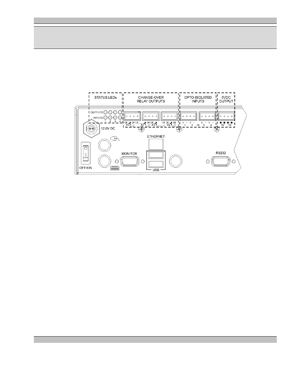
GPIO Physical Interface
NOTE: This chapter applies to the MS9500GL only - the MS9500 does not accommodate GPIO.
Back view of the MS9500GL GPIO Interface:
The GPIO Control Interface offers opto-isolated inputs and relay change-over outputs that can be controlled via
third party show-control software, ESCAN or directly from the MS9500GL.
The Control Interface features:
Four Opto-Isolated inputs (each with a corresponding status LED) can be configured to provide triggers
to either an external show-control system or the MS9500GL directly.
Four Digital outputs (each with a corresponding status LED), each driving low current change-over relays
capable of switching up to 1A at 24VDC.
5VDC Power Supply to facilitate the I/O switch functioning.
Opto-Isolated Digital Inputs
The digital input connections consist of a bank of screw terminal connectors with separate 3.5mm removable
terminal blocks for ease of wiring. Each input is assigned two terminals indicated by a ‘+’ and ‘-‘ symbol.
Because each input is opto-isolated both connections must be used to ensure the correct operation of the input
circuit.
The MS9500GL GPIO utilizes four (4) digital input connection channels.
Input Circuit Wiring Configuration
The opto-isolated input circuits provide for various connection scenarios, two common methods follow: