Series dpb busway installation & operation manual – GE Industrial Solutions GE Zenith Series DPB User Manual
Page 74
66
Installation & Operation Manual, GE Series DPB Busway
March 25, 2013, Rev 0
GE Confidential
Series DPB Busway Installation & Operation Manual
BCMS Basic = Current Only
BCMS Plus = Current + Voltage
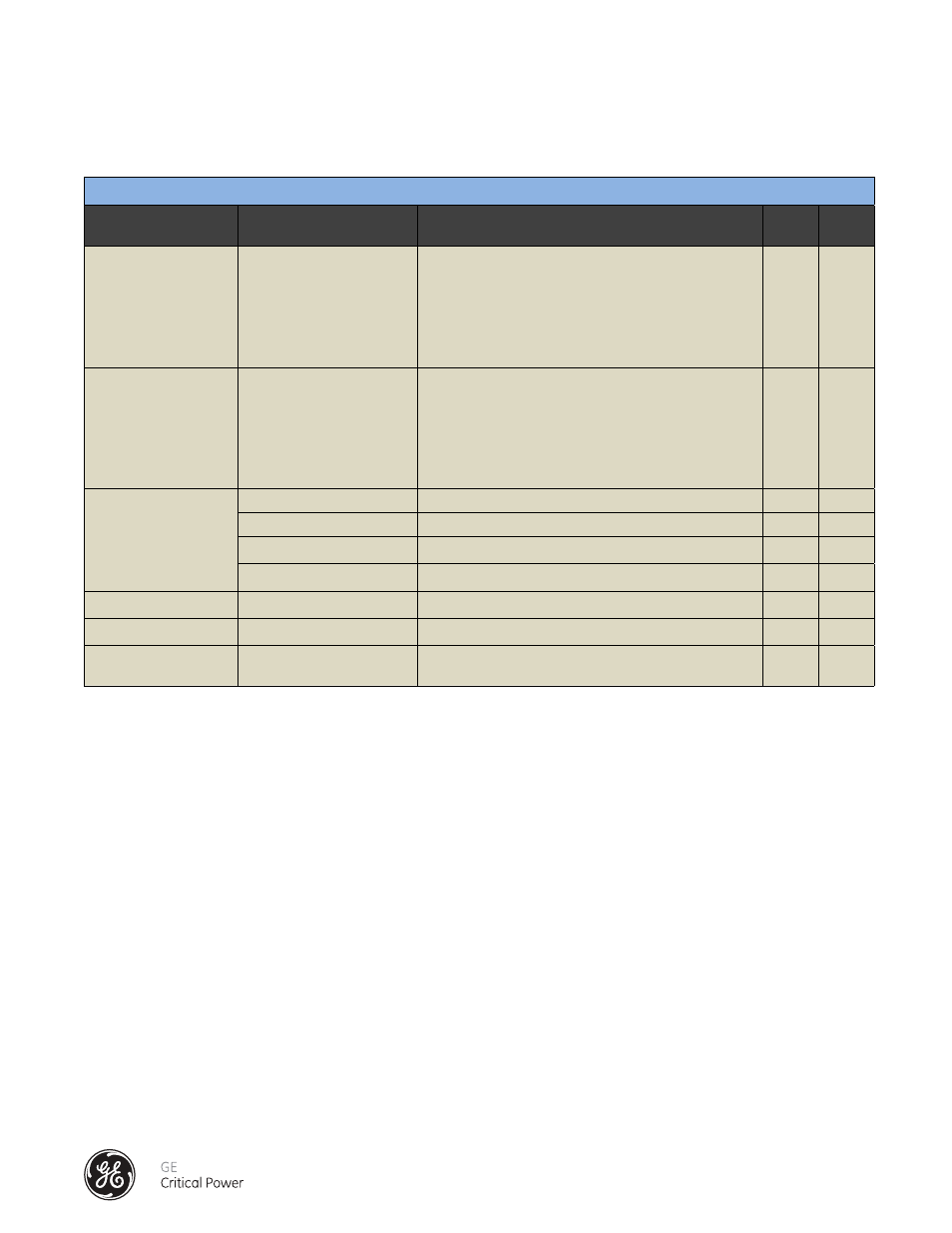
ALARM PARAMETERS
PARAMETER
DESCRIPTION
NOTES
BCMS
BASIC
BCMS
PLUS
Current Warning Alarm:
A, B, C (circuit breaker 1),
A, B, C (circuit breaker 2)
Indicates current exceeds user defined threshold (ex-
pressed as a percentage of circuit breaker rating).
Default rating is 70% of breaker capacity.
Alarm activates after a user defined time limit (default is
0 seconds)
a
a
Current High Alarm:
A, B, C (circuit breaker 1),
A, B, C (circuit breaker 2)
Indicates current exceeds user defined threshold (ex-
pressed as a percentage of circuit breaker rating).
Default rating is 85% of breaker capacity.
Alarm activates after a user defined time limit (default is
10 seconds)
a
a
Global Alarms:
Current Warning Alarm
Indicates if any current warning alarm is active.
a
a
High Current Alarm
Indicates if any high current alarm is active
a
a
Overvoltage Alarm
Indicates if any over voltage alarm is active
a
Undervoltage Alarm
Indicates if any under voltage alarm is active
a
Overvoltage Alarm:
(L-N Voltage)
Indicates voltage exceeds user defined threshold
a
Undervoltage Alarm:
(L-N Voltage)
Indicates voltage is below user defined threshold
a
Digital Input Alarm:
Digital inputs 1, 2, 3, 4
Indicates closed status of dry contact digital inputs (for
customer use)
a