Customer connections to 7" local display – GE Industrial Solutions GE Zenith Series DPB User Manual
Page 61
53
Installation & Operation Manual, GE Series DPB Busway
March 25, 2013, Rev 0
GE Confidential
Series DPB Busway Installation & Operation Manual
CUSTOMER CONNECTIONS TO 7" LOCAL DISPLAY
PRODUCT INTRODUCTION
The 7” Local Monitor Display is a high-performance, 800 x 480 pixel LED backlit color LCD display with a resistive touch
screen interface.
It is used with the Series DPB Busway to provide a graphic display of the detailed power parameter data for the busway
power source input (End Feed Boxes) and the branch circuits of the power distribution units (Tap Off Boxes).
The local monitor can be configured to display the power parameters of up to six End Feeds each with up to fifteen Tap Off
Boxes – a total of 96 device addresses.
POWER PARAMETERS MONITORED
End Feeds: (See Figure 49)
Voltage - (L-L, L-N, THD%, Freq.)
Current – (3 phases, N, G, Max., Demand, Crest Factor)
Power – (kW, kVA, kVAR, PF, kWH[A], kWH[B], kWH[C])
Percent Load – ( 3 phases)
Tap Off Boxes: (See Figure 50)
Voltage - (L-L, L-N, THD%, Freq.)
Current – (3 phases, N, G, Max., Demand, Crest Factor, for all poles)
Power – (kW, kVA, kVAR, PF, kWH[A], kWH[B], kWH[C] for all poles)
Percent Load – ( 3 phases for all poles)
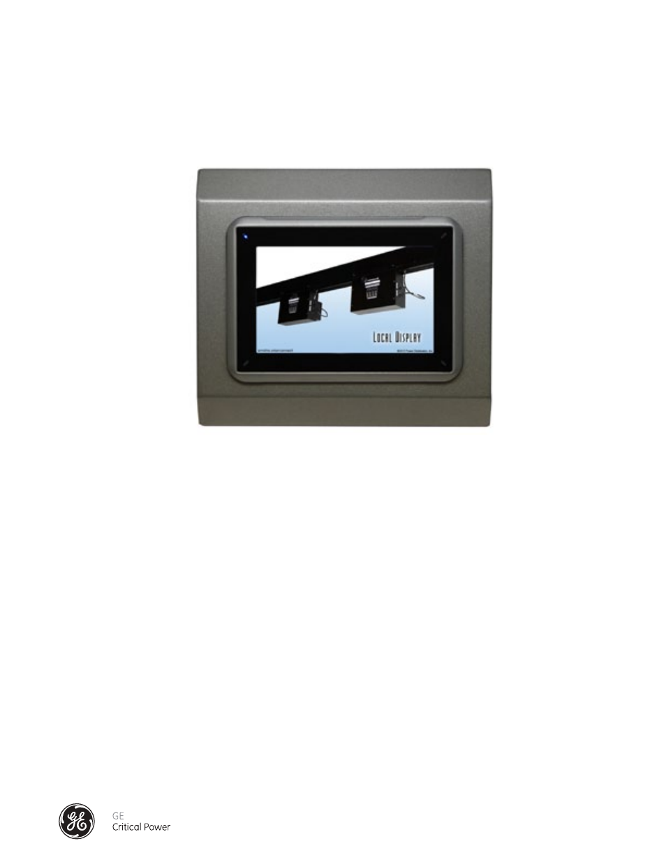
Figure 48 - 7" Series DPB Bus Systems Local Display