Series dpb busway installation & operation manual – GE Industrial Solutions GE Zenith Series DPB User Manual
Page 26
18
Installation & Operation Manual, GE Series DPB Busway
March 25, 2013, Rev 0
GE Confidential
Series DPB Busway Installation & Operation Manual
vii) Rotate and remove the cam actuator tool in cam port #4, and insert it into cam port #6. Rotate the
steel tool in cam port #6 to expand the contact plates.
viii) Rotate the adjacent, non-metallic cam spacers (g & h), ¼ turn.
ix) Rotate and remove the cam actuator tools.
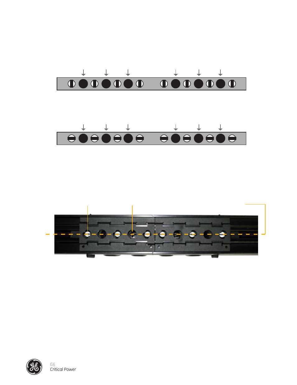
8.) CAUTION: DO NOT proceed to 9) Installation of the Dowel Pin Devices until the Cam Spacers are
verified to be in the locked position. A properly installed Splice, when viewed from the bottom (open
channel) of the joined bus sections will show the Cam Spacers in the Locked Position as show in Figure
15.1 below.
9.) Installation Of The Dowel Pin Devices
The Dowel Pins are used to secure open Cam Actuator Tool ports and add Cam Spacer functionality.
Material Required for Initial Installation (before busway is energized*):
Six Dowel Pin Devices
10) Inspect the busway, and verify that the splice connections of the busway have been installed correctly
per INSTALLATION OF THE SPLICE CONNECTOR – 400 AMP.
1. Verify no gaps between the bus connections
2. Verify the E-clips are positioned properly.
3. Verify the Cam Spacers (white-tipped, slotted lock pins) are positioned properly.
* please contact factory service for dowel pin installation procedure when working on an energized
busway (800-225-4838)
a
Cam
Port #1
Cam Spacers
bottom view
Cam
Port #2
b
c
d
e
f
g
h
Cam
Port #3
Cam
Port #4
Cam
Port #5
Cam
Port #6
a
Cam
Port #1
Cam Spacers
Cam
Port #2
b
c
d
e
f
g
h
Cam
Port #3
Cam
Port #4
Cam
Port #5
Cam
Port #6
1
2
3
4
5
6
1
2
3
4
5
6
a
Cam
Port #1
Cam Spacers
bottom view
Cam
Port #2
b
c
d
e
f
g
h
Cam
Port #3
Cam
Port #4
Cam
Port #5
Cam
Port #6
a
Cam
Port #1
Cam Spacers
Cam
Port #2
b
c
d
e
f
g
h
Cam
Port #3
Cam
Port #4
Cam
Port #5
Cam
Port #6
1
2
3
4
5
6
1
2
3
4
5
6
bottom view
cam spacer alignment before installation
cam spacer position - splice installation complete as seen from bottom
Figure 15 - Splice Installation Detail 400 Amp
Cam Spacer
Cam Actuator Tool Hole
Cams in Locked Position
Figure 15.1 - Cam Spacers in Locked Position