GE Industrial Solutions GE Zenith Series DPB User Manual
Page 21
13
Installation & Operation Manual, GE Series DPB Busway
March 25, 2013, Rev 0
GE Confidential
Series DPB Busway Installation & Operation Manual
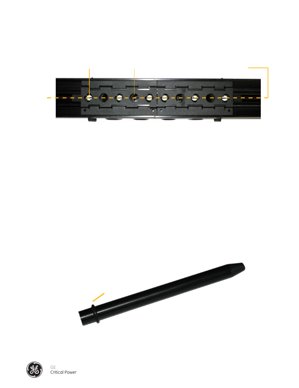
8.) CAUTION: DO NOT proceed to 9) Installation of the Dowel Pin Devices until the Cam Spacers are
verified to be in the locked position. A properly installed Splice, when viewed from the bottom (open
channel) of the joined bus sections will show the Cam Spacers in the Locked Position as show in
Figure 8.1 below.
9.) Installation Of The Dowel Pin Devices
The Dowel Pins are used to secure open Cam Actuator Tool ports and add Cam Spacer functionality.
Material Required for Initial Installation (before busway is energized*):
Four Dowel Pin Devices
10) Inspect the busway, and verify that the splice connections of the busway have been installed correctly
per INSTALLATION OF THE SPLICE CONNECTOR – 160 to 250 AMP.
1. Verify no gaps between the bus connections
2. Verify the E-clips are positioned properly.
3. Verify the Cam Spacers (white-tipped, slotted lock pins) are positioned properly.
*please contact factory service for dowel pin installation procedure when working on an energized
busway (800-225-4838)
11.) Each Dowel Pin has an O-ring set into a small groove on the insertion end of the dowel pin.
(See Figure 8.2).
Figure 8.1 - Cam Spacers in Locked Position
Figure 8.2 - Dowel Pin
O-Ring
Cam Spacer
Cam Actuator Tool Port
Cams in Locked Position