Option 1 - tap off box monitoring only – GE Industrial Solutions GE Zenith Series DPB User Manual
Page 42
34
Installation & Operation Manual, GE Series DPB Busway
March 25, 2013, Rev 0
GE Confidential
Series DPB Busway Installation & Operation Manual
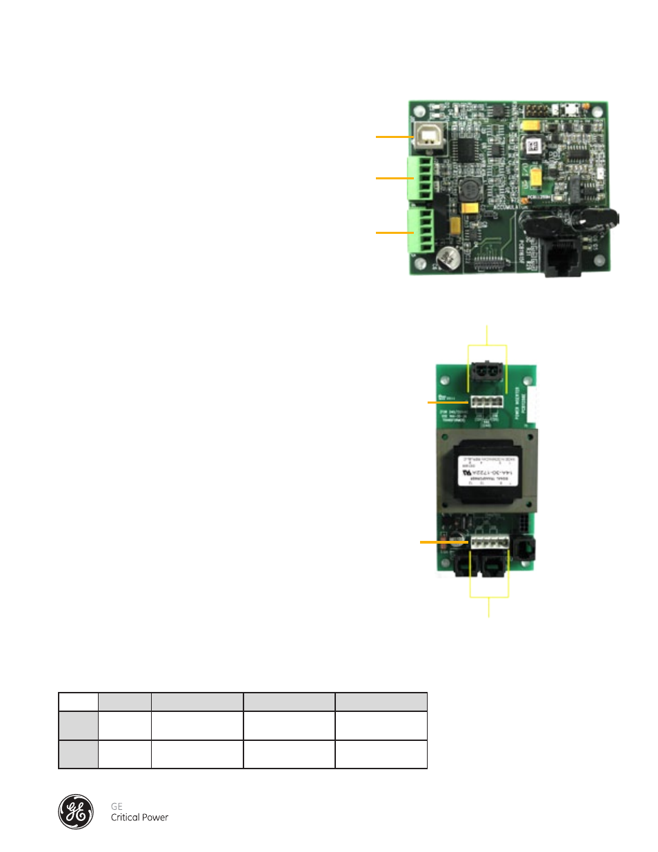
ACCUMULATOR PCB
All communications (power data) from the
Tap Off Boxes are transmitted through the
Accumulator Board (Figure 25). The board
is equipped with a RS-485 serial Modbus
communications serial interface capable of
two-wire or four-wire communications. Refer to
Section "Communications" for details on how to
interface with the serial port for connection to
Building Management Systems (BMS),
Data Center Infrastructure Solutions (DCIM) or
Local Displays.
POWER INSERTER PCB
DC power for all related circuit boards of the Bus
Monitoring System is supplied through the Power
Inserter Board (Figure 26) located inside the BCMS
Monitoring Module on the End Feed Box. The Power
Inserter Board acquires AC power via a readily accessible
disconnect device directly from the End Feed main AC
input bus. It provides a 24 VDC source along the bus rail
communications cable to power the intelliBUS (Branch
Monitoring) circuit boards in Tap Off Boxes. It is important
that the Power Inserter be configured for the correct
AC input voltage. See Table 1. For the correct jumper
configuration for jumper J2 and J5 located on the Power
Inserter Board.
The input power inserter is always fused with Type KTK-R fuses rated at 0.5A.
480 VAC
380VAC
240VAC
208VAC
J2
2 to 3
2 to 3
1 to 2 and 3 to 4 1 to 2 and 3 to 4
J5
2 to 3
1 to 2 and 3 to 4
2 to 3
1 to 2 and 3 to 4
Table 1 - Power Supply Input Voltage Configuration
J6 Modbus
Serial Output
J8 USB Port
J5 Modbus
Serial Input
J2 Voltage
Configuration
J5 Voltage
Configuration
Figure 25 - Accumulator PCB
Figure 26 - Power Inserter PCB
1 2 3 4
Jumper Pins
12345
Jumper Pins
Option 1 - TAP OFF BOX MONITORING ONLY