Ae e b 1 2 c d – GE Industrial Solutions GE Zenith Series DPB User Manual
Page 19
11
Installation & Operation Manual, GE Series DPB Busway
March 25, 2013, Rev 0
GE Confidential
neutral
N
C
A
B
neutral
N
A
C
B
neutra
l
Series DPB Busway Installation & Operation Manual
INSTALLATION OF THE SPLICE CONNECTOR – 160 - 250 AMP
All busway sections are shipped from the factory with one splice pack assembly. As each busway section is
mounted on its hanger supports, the abutting end of the splice section can be installed to
the adjoining busway section.
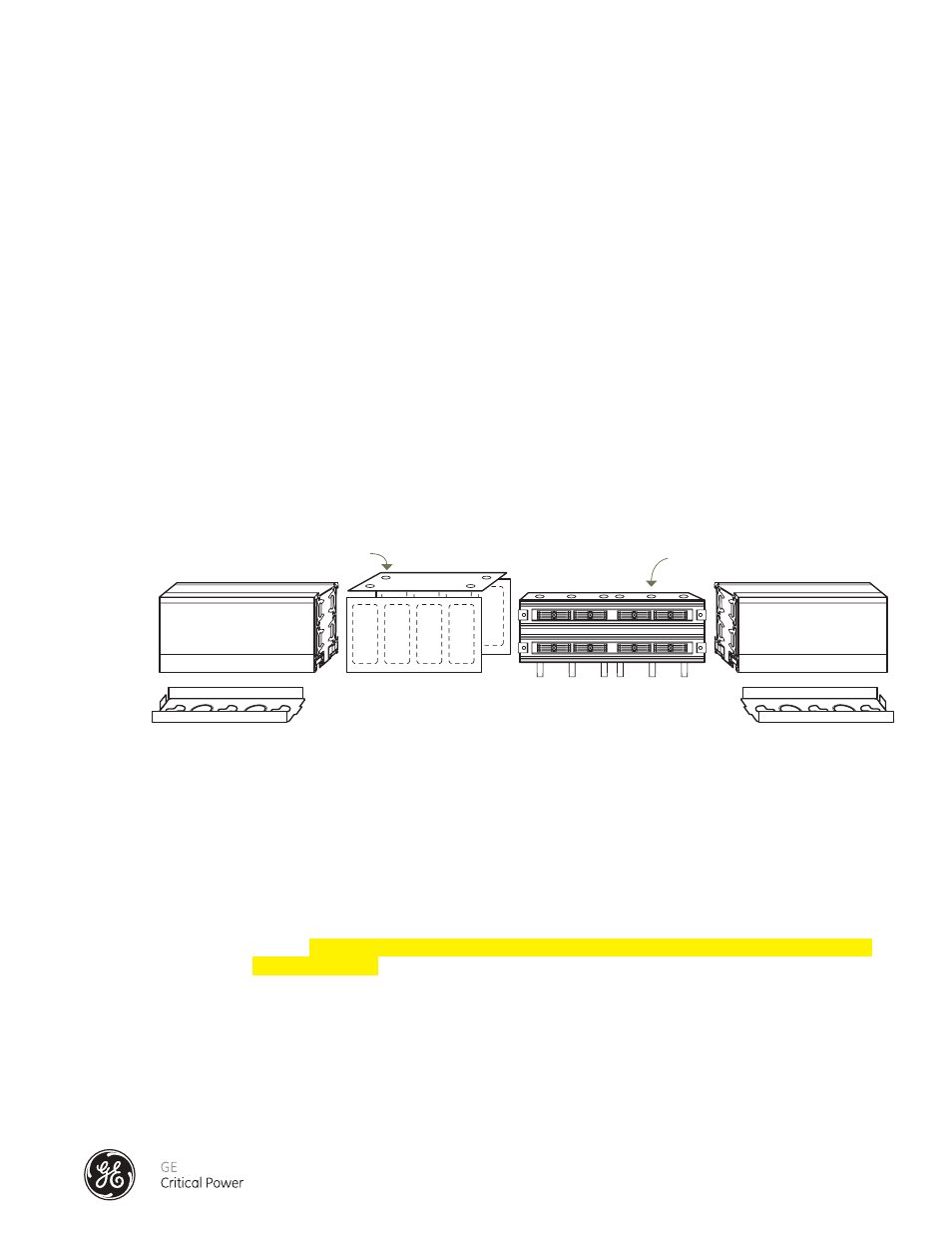
Connection of Busway Sections and Fittings: (See Figure 7)
1) Each section of busway will come with one Splice Pack assembly (D) and two "E" Clips (E) one at each
end of the bus section. Make sure the “E” Clips are always installed on each end of each rail.
2) Bus sections are phase-keyed to maintain proper circuit phasing of the run.
3) Section 2 (with the splice) and Section 1 (without splice) will be aligned on their respective supports. Slide
Section 1 forward on the splice pack.
4) Slide Splice Joint Covers (B & C) and "E" Clip (E) into place positioning them equally across the bus.
5) Slide Grounding Plate (A) into place and secure the four grounding screws to the busway.
Torque values for the set screws is 60 in-lbs minimum and a maximum of 85 in-lbs.
6) Slide the Splice Pack Assembly so that it is positioned equally on either side of the bus section joint.
7) Starting from one end of the Splice Pack (Figure 8), only use the steel cam-actuator tools supplied to
expand the splice joint contact assemblies into contact with bus sections bus bars.
i) Insert one tool into the first cam port #1; the second cam-actuator tool into the adjacent cam port
#2. Rotate each tool ¼ turn to expand the contact plates.
ii) Rotate the adjacent, non-metallic cam spacers (a & b), ¼ turn to hold the expanded contact plate
in place. DO NOT ATTEMPT TO USE THE NON-METALLIC CAMSPACERS TO EXPAND THE CONTACT
PLATE ASSEMBLIES.
iii) Rotate and remove the cam actuator tool in cam port #1, and insert it into cam port #3. Rotate the
steel tool in cam port #3, 1/4 turn clockwise to expand the contact plates.
iv) Rotate the adjacent, non-metallic cam spacers (c & d), 1/4 turn clockwise.
v) Rotate and remove the cam actuator tool in cam port #2, and insert it into cam port #4. Rotate the
steel tool in cam port #4 to expand the contact plates.
vi) Rotate the adjacent, non-metallic cam spacers (e & f), 1/4 turn clockwise.
vii) Rotate and remove the cam actuator tools.
A Top Grounding Plate with set screws
B Side Cover Support Plate
C Side Cover Support Plate
D Splice Pack Assembly
E “E” clip
1 Bus Section
2 Bus Section
A
E
E
B
1
2
C
D
Allen-head screws
Splice Pack
Figure 7 - Splice Installation Overview 160 - 250 Amp