Caution – GE Industrial Solutions GE Zenith Series DPB User Manual
Page 49
41
Installation & Operation Manual, GE Series DPB Busway
March 25, 2013, Rev 0
GE Confidential
Series DPB Busway Installation & Operation Manual
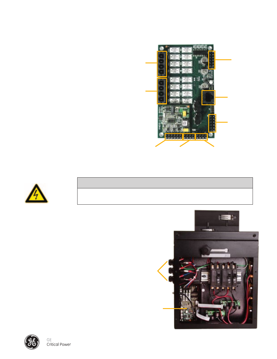
INPUT PM PCB
Input Power Monitor (PM) Board: (Figure 38):
this board monitors two separate 3- phase
power sources including voltage, phase
current and neutral, and ground current as
well as four contact alarm inputs.
SAFETY WARNING
CAUTION
ALL VOLTAGE CONNECTIONS MUST BE FUSED!
TAP OFF BOX MONITORING COMPONENTS
Each Tap Off Box is BCMS-equipped (Figure 39)
and interconnected with the Accumulator Board
via the Communications Cable Connection
scheme (Figure 40).
Branch Monitor Sensor Board (intelliBUS): This
board monitors 3- phase current (phases A, B,
C) for each branch circuit. Depending on the
configuration of the system, not all current
sensors may be employed.
Fusing: The Branch Circuit Monitoring system uses
three fuses (one per phase) to protect the voltage
sensing circuits. Fuses are located on the side of
the Tap Off Box (Figure 34) in screw-type safety
fuses holders. Fuses are Type KTK-R rated at 0.5A.
Note that the state of a fuse on the sensing circuit
will not affect the electrical performance of the
Series DPB Bus System.
J9 Voltage
Configuration
J8 Voltage
Configuration
J11 Input
Current 2
(A, B, C)
J3 CanBUS
Modbus Power
J7 External
Contacts
J10 Input
Current 1
(A, B, C)
J13 Input
Current 2
(N, G)
J12 Input
Current 2
(N, G)
Figure 38 - Input PM PCB
Fuses
IntelliBUS PCB
Figure 39 - Tap Off Box with Branch Circuit Monitoring Installed
Option 3 - TAP OFF BOX AND END FEED MONITORING CONCURRENTLY