GE Industrial Solutions GE Zenith Series DPB User Manual
Page 52
44
Installation & Operation Manual, GE Series DPB Busway
March 25, 2013, Rev 0
GE Confidential
Series DPB Busway Installation & Operation Manual
CONNECTING THE END FEED BOX TO LOCAL DISPLAYS OR BMS / DCIM SOLUTIONS
Practical operational limits of Modbus are thirty-two devices on a chain which means thirty-two Accumulators can be
connected together. Each device has its own address that limits the number of Accumulators you can have on any Modbus
chain.
There are two communications ports on the Accumulator Board in the End Feed Box for customer communications, J5 and
J6. They are both in parallel, so the End Feeds can be connected in a Modbus daisy chain up to the limits detailed above. The
first port (J6) is dedicated to supplying data to an upstream device acquiring the information. The second port (J5) is used to
link additional acquisition circuit boards to allow a single communications port for multiple boards. Refer to Figure 38 for the
location of the serial port terminal blocks. Be sure to observe polarities and connection points marked on the circuit board
when connecting to the serial port.
The Input Power Monitoring Board in the End Feed and the iBus Board in the Tap Off Boxes have the capability to monitor
multiple sources. The End Feed can monitor two independent three phase sources so designed for a dual bus End Feed.
The iBus Board can monitor 6 currents, two of each phase.
The USB communications port is reserved for factory programming and customization of module parameters. Consult the
External Interface Manual for details.
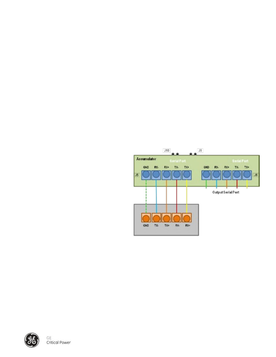
RS 485 FOUR-WIRE CONNECTION
The four-wire configuration is connected as shown
in Figure 41. When daisy chaining additional
accumulator boards, the output from the first
board (
J5) is connected to the input of the second
board (J6). The output going to the serial port of the
external acquisition device, i.e. Modbus™ gateway,
is always connected to
J5 of the last board in the
series of boards.
Note(s): Up to 18 boards may be connected on one
string. Jumpers on J9 and J10 must be removed.
If you require a Ground connection, then you
can hook up the Ground connection, but it is not
required.
Customer Building
Management System
Accumulator or
BCMS Hub
Figure 41 - RS485 Four-Wire Connection Scheme