Caution, Option 2 - end feed monitoring only – GE Industrial Solutions GE Zenith Series DPB User Manual
Page 44
36
Installation & Operation Manual, GE Series DPB Busway
March 25, 2013, Rev 0
GE Confidential
Series DPB Busway Installation & Operation Manual
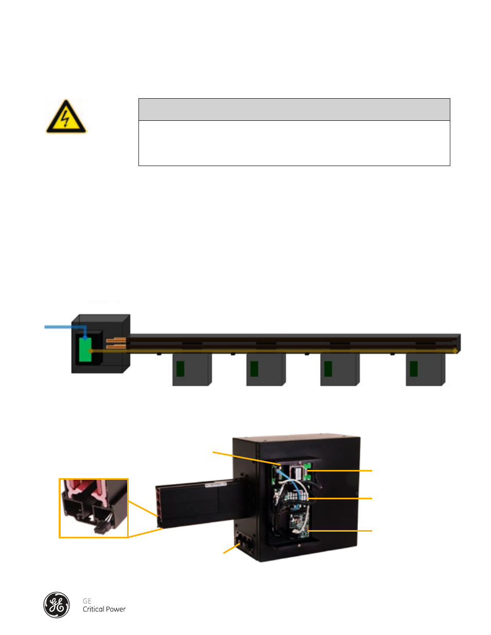
Option 2 - END FEED MONITORING ONLY
SAFETY WARNING
CAUTION
SEVERE INJURY OR DEATH CAN RESULT FROM ELECTRICAL SHOCK DURING CONTACT WITH
HIGH VOLTAGE CONDUCTORS, MONITORING PCBS, OR RELATED EQUIPMENT. DISCONNECT
AND LOCK OUT ALL POWER SOURCES DURING INSTALLATION AND SERVICE.
END FEED BOX COMPONENTS
The Option 2 configuration (Figure 29) is intended for monitoring of the busway power input only. Only the data acquisition
boards located in the End Feed are utilized for the Busway Input Feeder monitoring.
The End Feed Box contains the main data acquisition system consisting of an Accumulator PCB, a Power Inserter PCB, and
an Input PM PCB (Figure 30). The power disconnects for the circuit boards are the readily accessible fuses mounted on the
outside of the End Feed Box. Ingress to these circuit boards is by removing the cover on the restricted-access Bus Monitor
Housing.
This should only be done by a qualified electrical technician as removing the cover will expose high voltage
connections on the circuit boards. If the system logic PCBs have been purchased separately, they must be mounted in an
access-restricted, grounded metal box and a readily accessible appropriate upstream power disconnect must be provided.
For details on the circuit board parameters reference Appendix B: End Feed (Input PM Board) Monitoring Specifications.
Bus Monitor Fuse Access
Power Inserter PCB
Input PM PCB
Accumulator PCB
Bus Monitor Module (Cover
Removed)
Communications Cable
End Feed
Tap Off Box
Tap Off Box
Tap Off Box
Tap Off Box
Busrail
Figure 29 - Option 2 - Busway Input Feeder Monitoring
Figure 30 - Option 2 - End Feed Box Bus Monitoring Components