GE Industrial Solutions GE Zenith Series DPB User Manual
Page 23
15
Installation & Operation Manual, GE Series DPB Busway
March 25, 2013, Rev 0
GE Confidential
E Clip
Series DPB Busway Installation & Operation Manual
INSTALLATION OF OPTIONAL "C-CLIPS" FOR 35kAIC RATED 400A BUSWAY
The 35 kAIC rated 400A Busway utilizes a C-Clip to control tolerances in the busrail channel opening. Detailed below are the
modified installation instructions to install these C-Clips on End Feeds and Busrails.
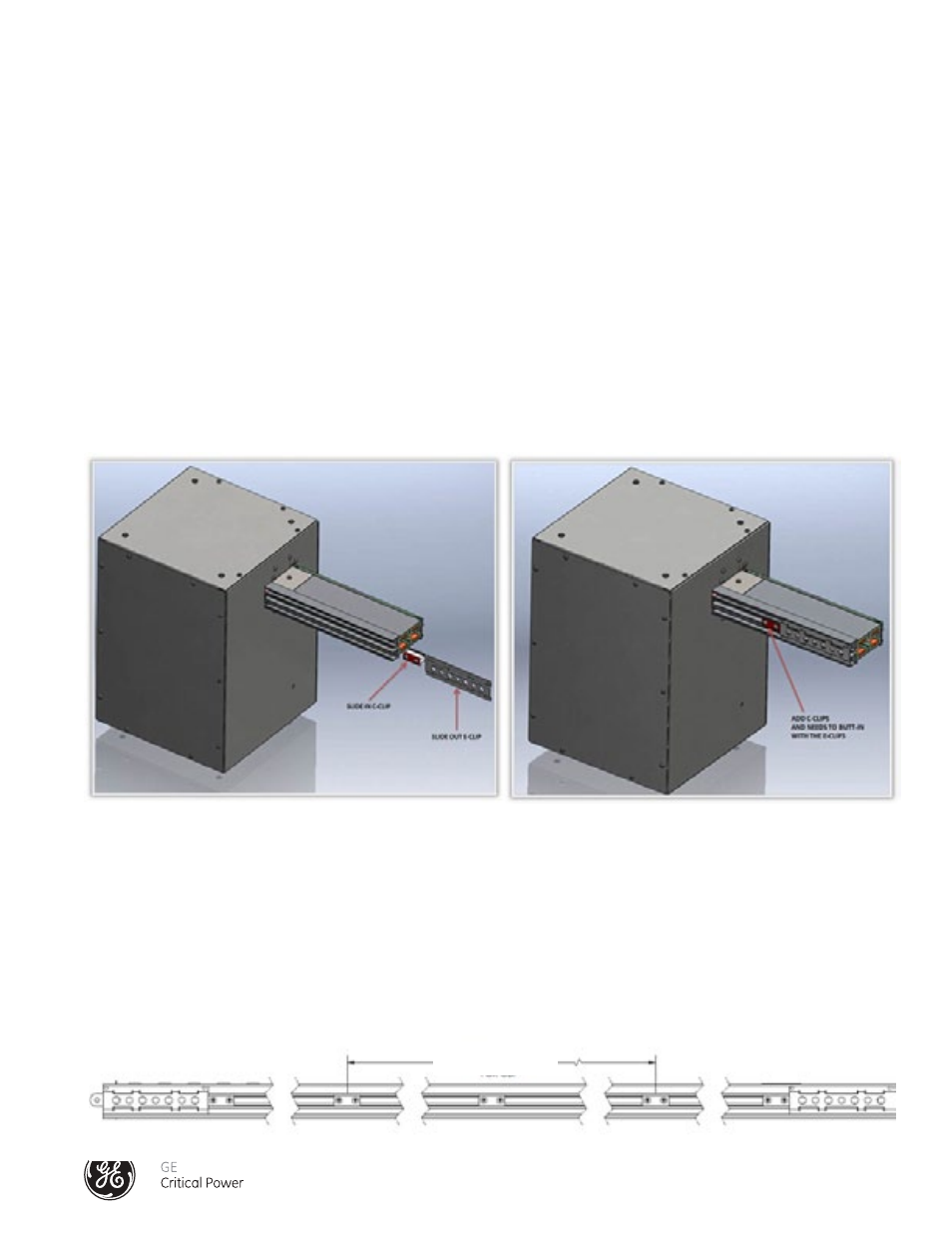
END FEED C-CLIP INSTALLATION
See Figure 9 - End Feed C-Clip Installation - 400 Amp
1.) Locate the C-clip
2.) Remove E-clip by sliding it off the bus rail of the End Feed
3.) Install the C-clip by sliding into place between the walls of the open channel.
4.) Reinstall the E-clip.
5.) Position C-clip so that that it butts up against the E-clip.
6.) Tighten screws on C-clip.
NOTE: Loosen, do not remove, the two screws of the C-clip assembly.
BUSRAIL AND SPLICE JOINT C-CLIP INSTALLATION
Install C-clips at the prescribed locations on the bus rail. (See Figure 10 - Busrail C-Clip Installation - 400 Amp).
1.) A C-clip should be placed approximately every 31.5" along the busrail or 2 x 31.5" (63") Pitch Location For Clip. If Tap Off
Boxes are installed in the busrail and meet the 31.5" requirement then a C-clip is not required. If a 31.5" opening exists along
the busrail then a C-clip will need to be installed.
NOTE: Loosen, do not remove, the two screws of the C-clip assembly.
Figure 9 - End Feed C-clip Installation - 400 Amp
Figure 10 - Busrail C-Clip Installation - 400 Amp
2x31.5" (63")
Pitch Location For Clip