Installation of the end cap closure plate – GE Industrial Solutions GE Zenith Series DPB User Manual
Page 28
20
Installation & Operation Manual, GE Series DPB Busway
March 25, 2013, Rev 0
GE Confidential
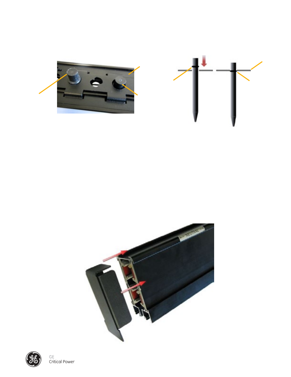
Figure 16 - Busrail End Cap Installation
Series DPB Busway Installation & Operation Manual
14.) Insert another Dowel into the next empty port on the splice. (Six empty tool ports per 400A splice
connection). Make sure that the O-ring on the dowel is inside the black bracket (E-clip) (See Figure 15.5)
15.) Repeat Step 13 until all the vacant Cam-Actuator Tool ports have Dowel Pins in them.
16.) Repeat the process for each splice in the bus run until complete.
16) Repeat the process for each splice in the bus run until complete.
INSTALLATION OF THE END CAP CLOSURE PLATE
Always terminate each busway run with an end cap in order to prevent any contact with live
conductors or internal components inside the extruded aluminum busrail housing. See Figure 16.
To install, align side and top tabs with channels on busrail and tap in using a rubber mallet until flush.
The method of installation of the end caps is common for all mounting positions.
Figure 15.5 - Dowel Pin O-Ring Inside "E" Clip
E Clip
E Clip
Before
After
Before
After