Flight instruments, Turn rate indicator – Garmin G1000 Quest Kodiak User Manual
Page 54
Garmin G1000 Pilot’s Guide for the Quest Kodiak 100
190-00590-00 Rev. C
2-10
FLIGHT INSTRUMENTS
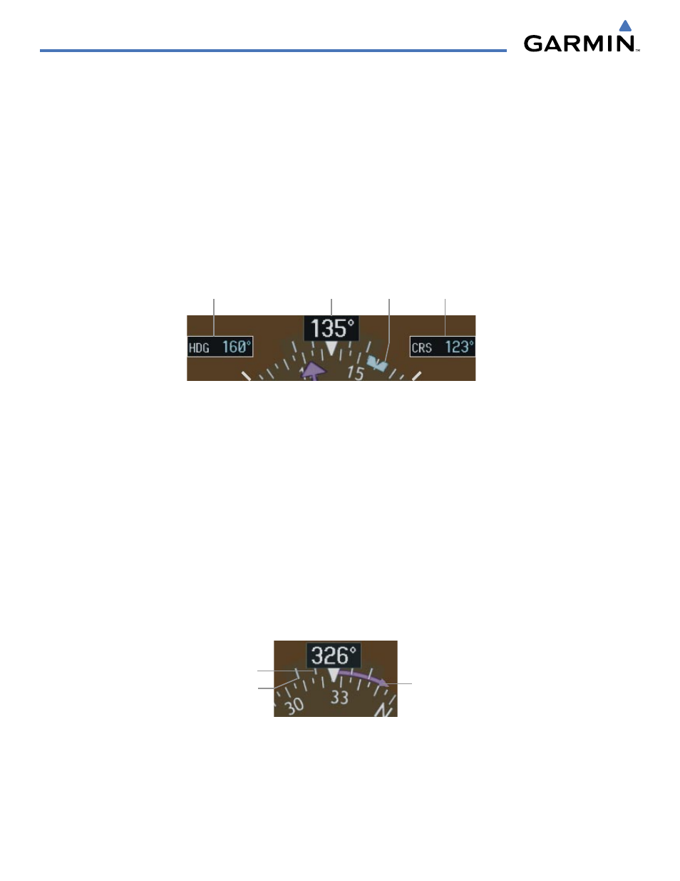
A digital reading of the current magnetic heading appears on top of the HSI. The heading displayed on the
HSI is always magnetic, even if the NAV ANGLE is set to ‘TRUE’ on the AUX - System Setup Page on the MFD
(see the System Overview for details).
When a course is selected by rotating the CRS Knob, a digital reading appears for 3 seconds in a box to the
right of the lubber line, next to the HSI. Pressing the CRS Knob displays the digital reading, re-centers the CDI,
and returns the course pointer pointing to the bearing of the active waypoint or navigation station (see OBS
Mode for information on adjusting a GPS course).
When a heading is selected by rotating the HDG Knob, a digital reading appears for 3 seconds in a box to the
left of the lubber line, next to the HSI. A rotatable heading bug marks the desired heading on the HSI. This
Selected Heading Bug and the current aircraft heading can be synchronized by pressing the HDG Knob, which
moves the bug to the current heading.
Figure 2-16 Heading and Course Indications
Selected
Heading
Selected
Course
Current
Heading
Selected
Heading Bug
The following annunciations appear in yellow on the HSI to indicate abnormal GPS conditions:
• ‘INTEG’: Loss of Integrity–GPS integrity is insufficient for the current phase of flight (see Figure 2-20)
• ‘WARN’: GPS position error
TURN RATE INDICATOR
The Turn Rate Indicator is located directly above the rotating compass card. Tick marks to the left and right
of the lubber line denote half-standard and standard turn rates. A magenta Turn Rate Trend Vector shows the
current turn rate. The end of the trend vector gives the heading predicted in 6 seconds, based on the present
turn rate. A standard-rate turn is shown on the indicator by the trend vector stopping at the standard turn
rate tick mark, corresponding to a predicted heading of 18˚ from the current heading. At rates greater than
4 deg/sec, an arrowhead appears at the end of the magenta trend vector and the prediction is no longer valid
(Figure 2-17).
Figure 2-17 Turn Rate Indicator and Trend Vector
Half-std Turn Rate
Std Turn Rate
Arrow Shown
for Turn Rate >
4 deg/sec