1 flight instruments, Airspeed indicator, 1 flight instruments -4 – Garmin G1000 Quest Kodiak User Manual
Page 48: Flight instruments
Garmin G1000 Pilot’s Guide for the Quest Kodiak 100
190-00590-00 Rev. C
2-4
FLIGHT INSTRUMENTS
2.1 FLIGHT INSTRUMENTS
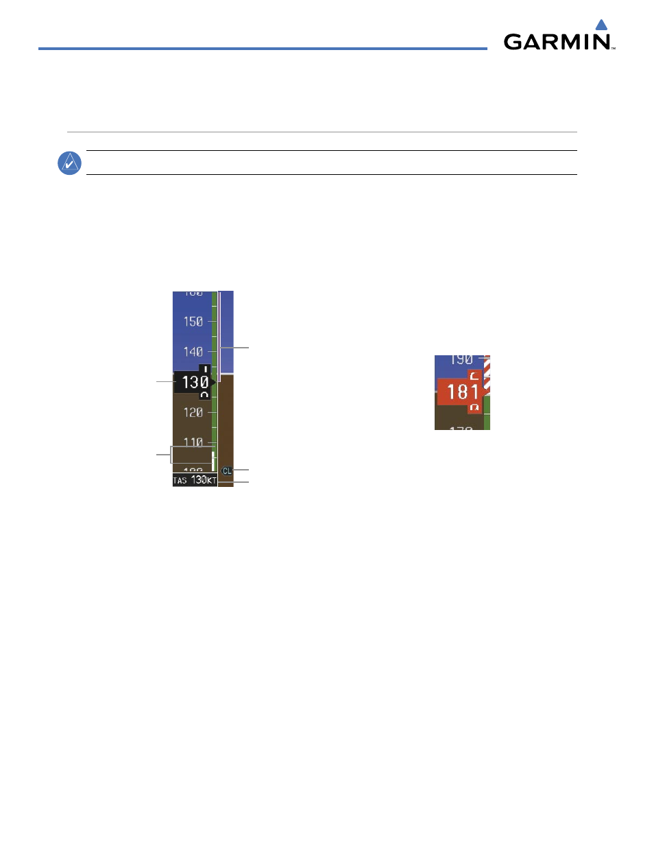
AIRSPEED INDICATOR
NOTE:
Refer to the Aircraft Flight Manual (AFM) for speed criteria and Vspeed values.
The Airspeed Indicator displays airspeed on a rolling number gauge using a moving tape. The true airspeed
(TAS) is displayed in knots below the Airspeed Indicator.
The numeric labels and major tick marks on the moving tape are marked at intervals of 10 knots, while minor
tick marks on the moving tape are indicated at intervals of 5 knots. Speed indication starts at 20 knots, with 60
knots of airspeed viewable at any time. The actual airspeed is displayed inside the black pointer. The pointer
remains black until reaching maximum operating speed (V
MO
), at which point it turns red (Figure 2-4).
Figure 2-4 Red Pointer at V
MO
Figure 2-3 Airspeed Indicator
Actual
Airspeed
Airspeed
Trend Vector
True Airspeed
Vspeed Reference
Speed
Ranges
A color-coded (white, green, and red/white striped) speed range strip is located on the moving tape. The
colors denote flaps operating range, normal operating range, and maximum operating speed (V
MO
). A red
range is also present for low speed awareness.
The Airspeed Trend Vector is a vertical, magenta line, extending up or down on the airspeed scale, shown
to the right of the color-coded speed range strip. The end of the trend vector corresponds to the predicted
airspeed in 6 seconds if the current rate of acceleration is maintained. If the trend vector crosses V
MO
, the text
of the actual airspeed readout changes to yellow. The trend vector is absent if the speed remains constant or
if any data needed to calculate airspeed is not available due to a system failure.