Toshiba – Toshiba Adjustable Speed Drive H3 User Manual
Page 35
TOSHIBA
7 - 4
MONITORING "RR" INPUT SPECIAL FUNCTION
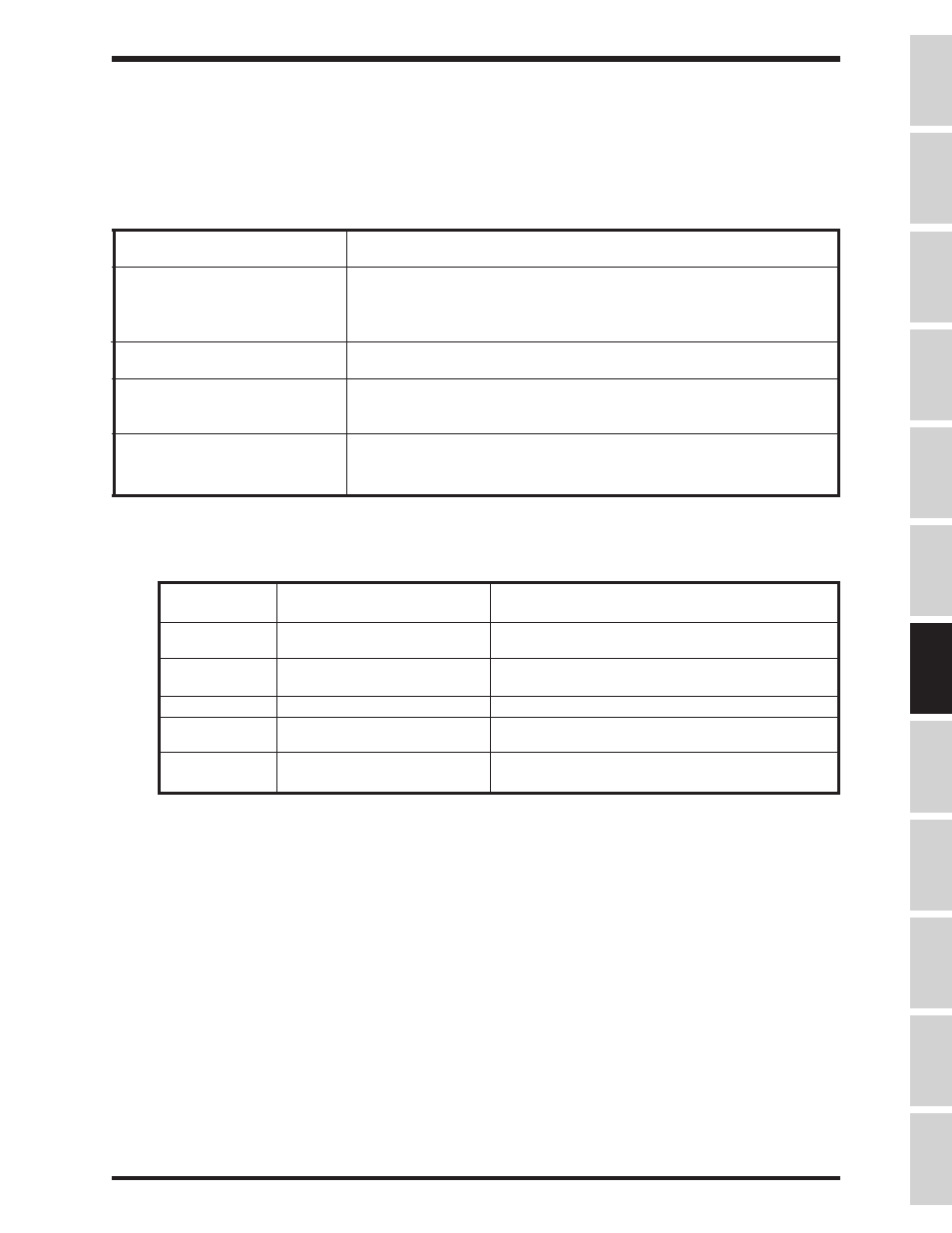
The "RR" terminal can be used to adjust the following drive parameters on the fly: Maximum
Output Frequency, accel/decel times, voltage boost, and stall level. When Item 289, 290, 291, or
292 are programmed to "14", one of the drive's monitor windows will display the following:
Setting of Item 79
, RR INPUT
SPECIAL FUNCTION SELECT
Monitor display
1 With 10 volts on the "RR" terminal, this monitor shows
MAXIMUM
OUTPUT FREQUENCY
. Zero volts on "RR" makes the effective
Maximum Output Frequency 30 Hz. See Item 1,
MAXIMUM OUTPUT
FREQUENCY
.
2 This monitor displays the acc/dec multiplier. Zero volts on "RR" results
in a display of "1.0". Ten volts on "RR" results in a display of "10.0".
3 This monitor displays the effective voltage boost. Zero volts on the
"RR" terminal results in a "0.0" display. At ten volts,
VOLTAGE
BOOST
is displayed.
4 This monitor shows effective Stall Protection Current Level. If Item 296,
CURRENT UNITS SELECTION
is set to "1", no units will be
displayed with the current value.
MONITORING DURING PATTERN RUN
During a pattern run, the following four windows are added to the monitor sequence:
Key Operation
LCD Message
Explanation
OUTPUT FREQUENCY
Standard output frequency display
30.0HZ
MON
PATTERN GROUP #1
Indicates the active pattern group number
SPEED #3
and current speed used.
down arrow
NUMBER OF CYCLES
Indicates how many pattern group repetitions
REMAINING 145
are remaining
down arrow
PRESET SPEED # 12
Indicates the preset speed currently used.
down arrow
REMAINING PATTERN
Indicates the remaining pattern time
TIME
2365 MIN
down arrow
MOTOR RUN DIRECTION:
Beginning of regular monitor windows.
FORWARD
Specifications
Precautions
Wiring
Jumpers
Panel
Keypad
Parameters
Programming
Service
Dimensions
Index
Inspection