Introduction, About your video communications network, Example network diagram – TANDBERG D14049.04 User Manual
Page 84: Overview, Local zone
84
D14049.04
JULY 2008
Grey Headline (continued)
TANDBERG
VIDEO COMMUNICATIONS SERVER
ADMINISTRATOR GUIDE
Introduction
The most basic implementation of a TANDBERG
video communications network is a single VCS
connected to the internet with one or more
endpoints registered to it. However, depending
on the size and complexity of your enterprise
the VCS may be part of a network of endpoints,
other VCSs and other network infrastructure
devices, with one or more firewalls between it
and the internet. In such situations you may
wish to apply restrictions to the amount of
bandwidth used by and between different parts
of your network.
This section will give you an overview of the
different parts of the video communications
network and the ways in which they can be
connected. This information should allow you
to configure your VCS to best suit your own
infrastructure.
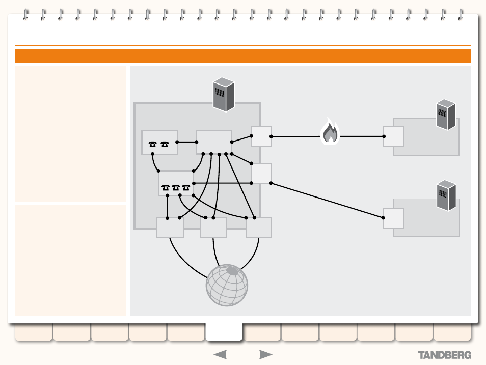
Example Network Diagram
The diagram opposite shows the different
components of a VCS (i.e. subzones and zones)
and how they interrelate. Using a VCS Control
as the example Local Zone, it shows that it is
made up of a number of subzones which are
all connected by links. The Local Zone is also
connected to external VCSs and to the internet
via different types of zones.
All these components are described in more
detail in the sections that follow.
About your Video Communications Network
VCS CONTROL
VCS EXPRESSWAY
Internet
VCS CONTROL
LOCAL ZONE
Traversal
Subzone
Default
Subzone
DNS
Zone
ENUM
Zone
Neighbor
Zone
Traversal
Client Zone
Neighbor
Zone
Traversal
Server Zone
Subzone
Default
Zone