Figure 26. filter specification – Intel 815 User Manual
Page 60
System Bus Design Guidelines
R
60
Intel
®
815 Chipset Platform Design Guide
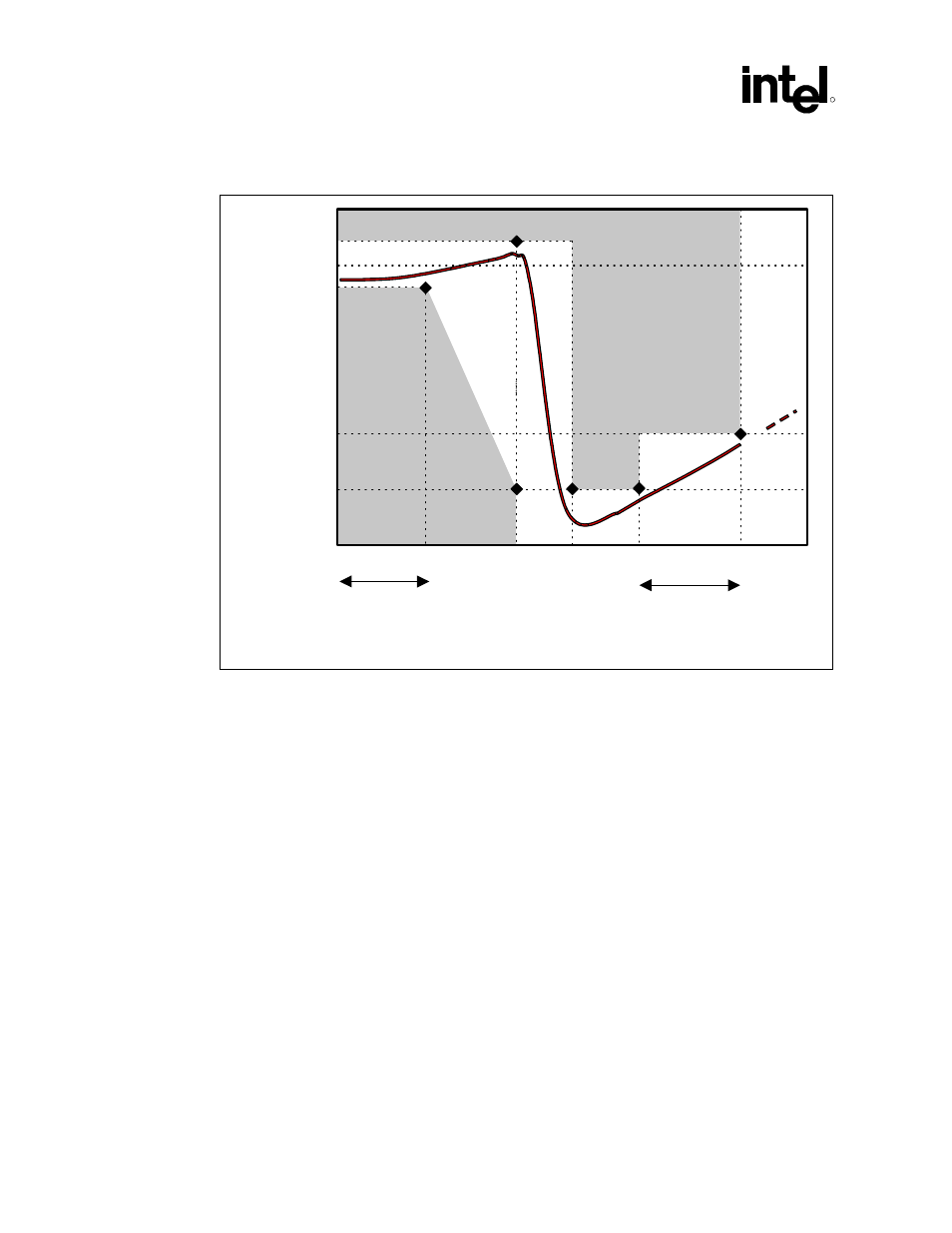
Figure 26. Filter Specification
0dB
-28dB
-34dB
0.2dB
-0.5 dB
1 MHz
66 MHz
fcore
fpeak
1Hz
DC
passband
high frequency
band
filter_spec
Forbidden
Zone
Forbidden
Zone
NOTES:
1. Diagram not to scale.
2. No specification for frequencies beyond fcore.
3. fpeak should be less than 0.05 MHz.
Other requirements:
•
Use shielded-type inductor to minimize magnetic pickup.
•
Filter should support DC current > 30 mA.
•
DC voltage drop from VCC to PLL1 should be < 60 mV, which in practice implies series
R < 2
Ω
. This also means pass-band (from DC to 1 Hz) attenuation < 0.5 dB for
VCC = 1.1V, and < 0.35 dB for VCC = 1.5V.
See also other documents in the category Intel Hardware:
- 41210 (64 pages)
- 8xC251TQ (20 pages)
- ENTERPRISE PRINTING SYSTEM (EPS) 4127 (84 pages)
- U3-1L (20 pages)
- 80960HA (104 pages)
- X58 (54 pages)
- ESM-2850 2047285001R (91 pages)
- ATOM US15W (54 pages)
- D915GVWB (4 pages)
- XP-P5CM-GL (28 pages)
- AX965Q (81 pages)
- CORETM 2 DUO MOBILE 320028-001 (42 pages)
- CV700A (63 pages)
- 80C188EA (50 pages)
- X25-M (28 pages)
- XP-P5IM800GV (26 pages)
- IB868 (60 pages)
- D865GVHZ (88 pages)
- IB865 (64 pages)
- Altera P0424-ND (1 page)
- 8086-2 (30 pages)
- IXDP465 (22 pages)
- IWILL P4D (104 pages)
- GA-8I955X PRO (88 pages)
- FSB400 (PC2100) (96 pages)
- D845GLAD (4 pages)
- NAR-3041 (1 page)
- 87C196CA (136 pages)
- G52-M6734XD (74 pages)
- A96134-002 (10 pages)
- Express Routers 9000 (8 pages)
- 82540EP (45 pages)
- D865GLC (94 pages)
- IB850 (69 pages)
- MB898RF (62 pages)
- Arima LH500 (78 pages)
- V09 (33 pages)
- I/O Processor (22 pages)
- M600 (110 pages)
- SE7520JR2 (63 pages)
- SERVER BOARD S5520HCT (30 pages)
- Extensible Firmware Interface (1084 pages)
- GA-8IPXDR-E (70 pages)
- D845EBG2 (4 pages)
- AW8D (80 pages)