Hub interface, Figure 53. hub interface signal routing example, 9 hub interface – Intel 815 User Manual
Page 107
Hub Interface
R
Intel
®
815 Chipset Platform Design Guide
107
9 Hub
Interface
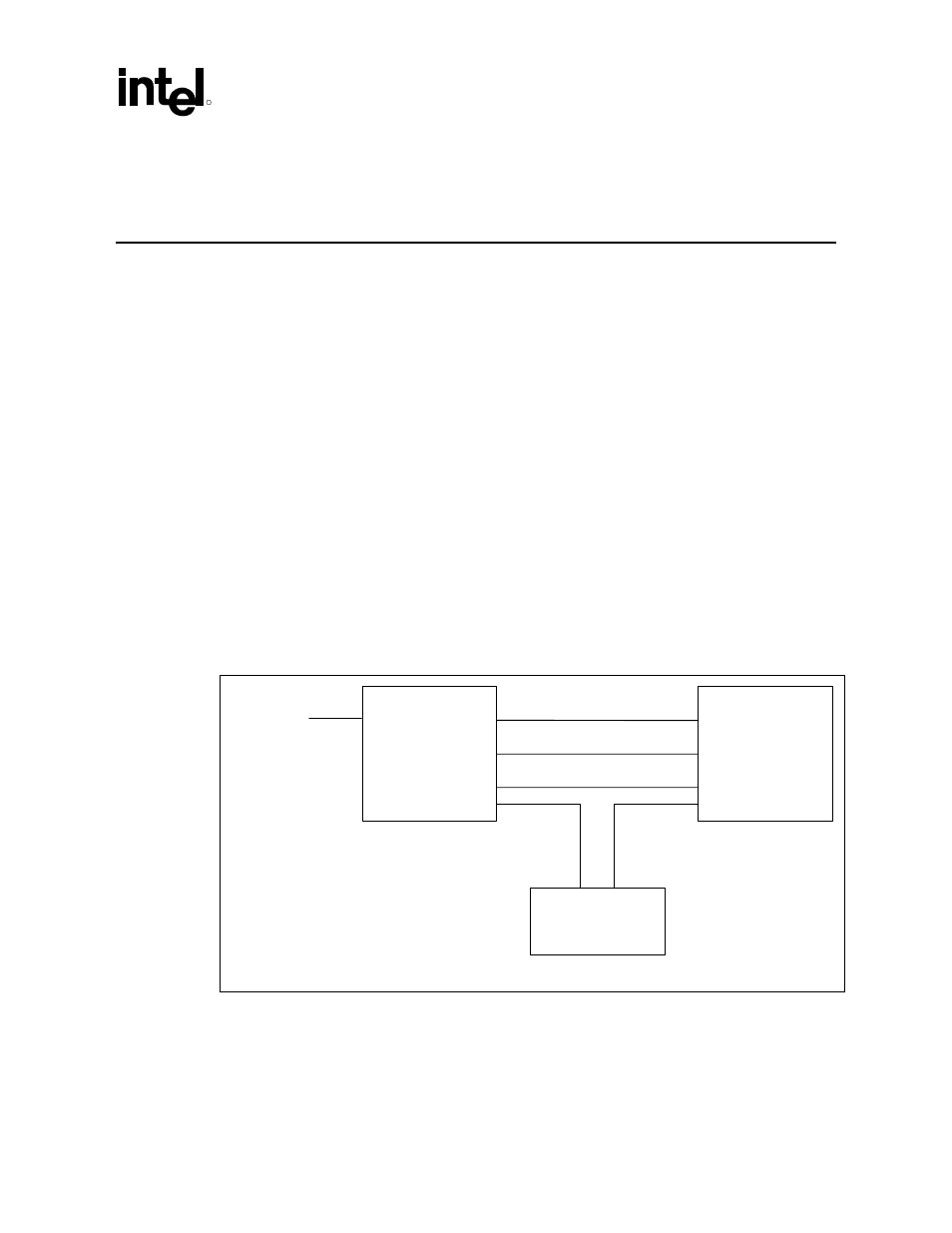
The GMCH ball assignment and the ICH ball assignment have been optimized to simplify hub
interface routing. It is recommended that the hub interface signals be routed directly from the
GMCH to ICH with all signals referenced to VSS (see Figure 53). Layer transition should be kept
to a minimum. If a layer change is required, use only two vias per net and keep all data signals and
associated strobe signal on the same layer.
The hub interface signals are divided into two groups: data signals (HL) and strobe signals
(HL_STB). For the 8-bit hub interface, HL[0:7] are associated with HL_STB and HL_STB#.
•
Data Signals:
HL[10:0]
•
Strobe Signals:
HL_STB
HL_STB#
Note: HL_STB/HL_STB# is a differential strobe pair.
No pull-ups or pull-downs are required on the hub interface. HL11 on the ICH should be brought
out to a test point for NAND Tree testing. Each signal should be routed such that it meets the
guidelines documented for its signal group.
Figure 53. Hub Interface Signal Routing Example
ICH
GMCH
Clocks
HL_STB
HL_STB#
HL[10:0]
CLK66
GCLK
HL11
hub link sig routin
NAND tree
test point