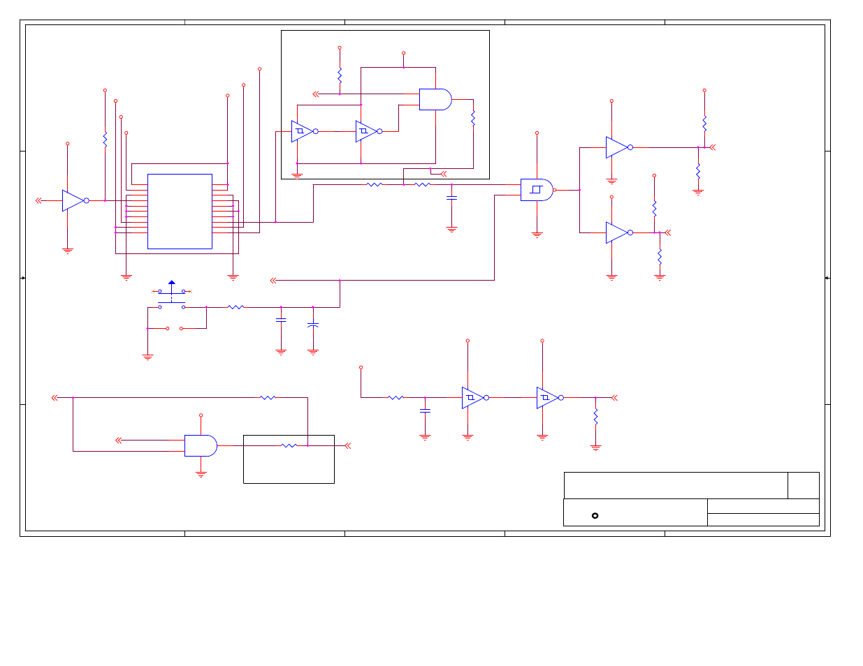
System, Intel, Power connector and reset control – Intel 815 User Manual
Page 208: System, part 2, Resume reset circuitry
5
5
4
4
3
3
2
2
1
1
D
D
C
C
B
B
A
A
SN74LVC06A has 5V
input tolerance
ITP RESET CIRCUIT - FOR DEBUG ONLY
DO NOT POPULATE R95
RESUME RESET CIRCUITRY
Schmitt Trigger Logic using a
22msec delay
Place JP13 Near Front Panel Header (J20)
Do Not Stuff R126 - For Test Only:
If R125 is Populated, R126
Must Be DE-Populated.
SN74LVC06A has 5V input
tolerance
1k Ohm Pull-up to 3.3V is on VRM Sheet
System
Power Connector and Reset Control
INTEL(R) 82815 CHIPSET CUSTOMER REFERENCE BOARD
SYSTEM, PART 2
40
1.0
3-26-01
35
Platform Apps Engineering
1900 Prairie City Road
Folsom, CA 95630
REV.
R
Last Revision Date:
Sheet:
of
Title:
intel
DBRST
DBRPOK_DLY
PWROK#
RST_PD
CK_PWRD
V3RSMRST
ST69
APOK_ST
ST23
5VPSON
ATX_PWOK
SLP_S3#
13,31
DBRPOK
DBRESET#
4
VRM_PWRGD
33
SLP_S3#
13,31
PWRGOOD
4
PWROK
13,30,31
RSMRST#
13,30
CK_PWRDN#
5
DBRPOK
VCC3SBY
VCC3SBY
VCC3SBY
VCC5SBY
VCC2_5
VCC3SBY
VCC3SBY
VCC3SBY
VCC3SBY
VCC3SBY
VCC5SBY
VCC12
VCC5SBY
VCC_5-
VCC12-
VCC3SBY
VCC3SBY
VCC3_3
VCC5
R344
1.8k
1
2
R302
R
1
2
R123
243
1
2
R95
0K
1
2
R87
20k
1
2
R88
4.7K
1
2
R62
330
1
2
R127
22K
1
2
R126
0K
1
2
R125
8.2K
1
2
R91
0K
1
2
SW 1
PBSWITCH
R81
22
1
2
R94
0K
1
2
R128
8.2k
1
2
C148
1.0UF
1
2
C248
1.0UF
1
2
C160
0.01UF
1
2
JP13
1
2
U10C
SN74LVC08A
10
9
8
14
7
U10B
SN74LVC08A
5
4
6
14
7
ATX
J5
1
2
3
4
5
6
7
8
9
10
11
12
13
14
15
16
17
18
19
20
3_3V1
3_3V2
GND3
5V4
GND5
5V6
GND7
PW_OK
5VB
12V
3_3V11
-12V
GND13
PS_ON
GND15
GND16
GND17
-5V
5V19
5V20
+
C161
10UF
1
2
U9B
74LS132
6
14
4
5
7
U7B
SN74LVC06A
4
14
7
3
U7A
SN74LVC06A
2
14
7
1
U7C
SN74LVC06A
6
14
7
5
U12D
74LVC14A
8
14
7
9
U12C
74LVC14A
6
14
7
5
U12B
74LVC14A
4
14
7
3
U12A
74LVC14A
2
14
7
1