Calculations – Intel 815 User Manual
Page 44
System Bus Design Guidelines
R
44
Intel
®
815 Chipset Platform Design Guide
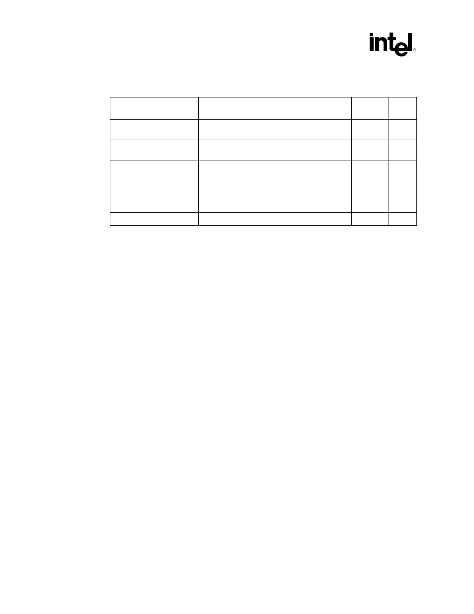
Table 6. Intel
®
Pentium
®
III Processor AGTL/AGTL+ Parameters for Example Calculations
IC Parameters
Intel
®
Pentium
®
III Processor at 133 MHz System
Bus
GMCH Notes
Clock to Output maximum
(T
CO_MAX
)
•
3.25 ns (for 66/100/133 MHz system bus speeds)
4.1 ns
1, 2
Clock to Output minimum
(T
CO_MIN
)
•
0.40 ns (for 66/100/133 MHz system bus)
1.05 ns
1, 2
Setup time (T
SU_MIN
)
•
1.20 ns (for BREQ Lines)
•
0.95 ns (for all other AGTL/AGTL+ Lines @
133 MHz)
•
1.20 ns (for all other AGTL/AGTL+ Lines @
66/100 MHz)
2.65 ns
1, 2,3
Hold time (T
HOLD
)
•
1.0 ns (for 66/100/133 MHz system bus speeds)
0.10 ns
1
NOTES:
1. All times in nanoseconds.
2. Numbers in table are for reference only. These timing parameters are subject to change. Check the
appropriate component datasheet for the valid timing parameter values.
3. T
SU_MIN
= 2.65 ns assumes that the GMCH sees a minimum edge rate equal to 0.3 V/ns.
Table 7 contains an example AGTL+ initial maximum flight time, and Table 8 contains an
example minimum flight time calculation for a 133 MHz, uniprocessor system using the Pentium
III processor and the Intel 815 chipset platform’s system bus. Note that assumed values were used
for the clock skew and clock jitter.
Note: The clock skew and clock jitter values depend on the clock components and the distribution
method chosen for a particular design and must be budgeted into the initial timing equations, as
appropriate for each design.
Table 7and Table 8 were derived assuming the following:
•
CLK
SKEW
= 0.20 ns (Note: This assumes that the clock driver pin-to-pin skew is reduced to
50 ps by tying the two host clock outputs together (i.e., “ganging”) at the clock driver output
pins, and that the PCB clock routing skew is 150 ps. The system timing budget must assume
0.175 ns of clock driver skew if outputs are not tied together as well as the use of a clock
driver that meets the Intel CK-815 Clock Synthesizer/Driver Specification.)
•
CLK
JITTER
= 0.250 ns
See the respective processor’s datasheet, the appropriate Intel 815 chipset platform documentation,
and the Intel
®
CK-815 Clock Synthesizer/Driver Specification for details on clock skew and jitter
specifications. Exact details regarding the host clock routing topology are provided with the
platform design guideline.