Atx power supply pwrgood requirements, Figure 72. pull-up resistor example, 2 atx power supply pwrgood requirements – Intel 815 User Manual
Page 145
Power Delivery
R
Intel
®
815 Chipset Platform Design Guide
145
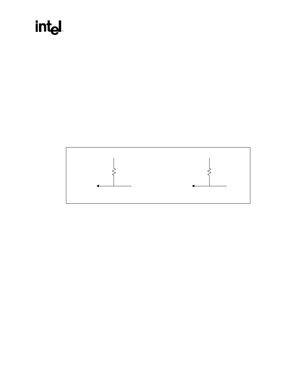
A simplistic DC calculation for a pull-up value is:
R
MAX
= (VCC
PU
MIN - V
IH
MIN) / I
LEAKAGE
MAX
R
MIN
= (VCC
PU
MAX - V
IL
MAX) / I
OL
MAX
Since I
LEAKAGE
MAX is normally very small, R
MAX
may not be meaningful. R
MAX
also is
determined by the maximum allowable rise time. The following calculation allows for t, the
maximum allowable rise time, and C, the total load capacitance in the circuit, including the input
capacitance of the devices to be driven, the output capacitance of the driver, and the line
capacitance. This calculation yields the largest pull-up resistor allowable to meet the rise time t.
R
MAX
= -t / (C * In(1-(V
IH
MIN / VCC
PU
MIN) ) )
Figure 72. Pull-Up Resistor Example
Vcc
pu
min.
R
max
V
IH
min.
I
Leakage
max.
Vcc
pu
max.
R
min
V
IL
max.
I
OL
max.
pwr_pullup_res
12.2
ATX Power Supply PWRGOOD Requirements
The PWROK signal must be glitch free for proper power management operation. The ICH sets the
PWROK_FLR bit (ICH GEN_PMCON_2, General PM Configuration 2 Register, PM-dev31:
function 0, bit 0, at offset A2h). If this bit is set upon resume from S3 power-down, the system will
reboot and control of the system will not be given to the program running when entering the S3
state. System designers should insure that PWROK signal designs are glitch free.