Tap controller state diagram figure 34-2 – Maxim Integrated DS21Q55 User Manual
Page 202
Product Preview
DS21Q55
202 of 248
012103
Please contact
or search
http://www.maxim-ic.com
for updated
information.
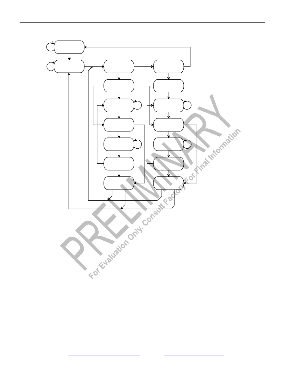
TAP CONTROLLER STATE DIAGRAM Figure 34-2
1
0
0
1
1
1
1
1
1
1
1
1
1
1
1
0
0
0
0
0
1
0
0
0
0
1
1
0
0
0
0
Select
DR-Scan
Capture DR
Shift DR
Exit DR
Pause DR
Exit2 DR
Update DR
Select
IR-Scan
Capture IR
Shift IR
Exit IR
Pause IR
Exit2 IR
Update IR
Test Logic
Reset
Run Test/
Idle
0