Maxim Integrated DS21Q55 User Manual
Page 163
Product Preview
DS21Q55
163 of 248
012103
Please contact
or search
http://www.maxim-ic.com
for updated
information.
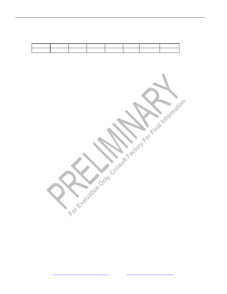
Register Name:
IMR1
Register Description:
Interrupt Mask Register 1
Register Address:
17h
Bit #
7
6
5
4
3
2
1
0
Name
-
TIMER
RSCOS
JALT
LRCL
TCLE
TOCD
LOLITC
Default
0
0
0
0
0
0
0
0
Bit 0/Loss of Transmit Clock Condition (LOLITC).
0 = interrupt masked
1 = interrupt enabled–generates interrupts on rising and falling edges
Bit 1/Transmit Open Circuit Detect Condition (TOCD).
0 = interrupt masked
1 = interrupt enabled–generates interrupts on rising and falling edges
Bit 2/Transmit Current Limit Exceeded Condition (TCLE).
0 = interrupt masked
1 = interrupt enabled–generates interrupts on rising and falling edges
Bit 3/Line Interface Receive Carrier Loss Condition (LRCL).
0 = interrupt masked
1 = interrupt enabled–generates interrupts on rising and falling edges
Bit 4/Jitter Attenuator Limit Trip Event (JALT).
0 = interrupt masked
1 = interrupt enabled
Bit 5/Receive Signaling Change Of State Event (RSCOS).
0 = interrupt masked
1 = interrupt enabled
Bit 6/Timer Event (TIMER).
0 = interrupt masked
1 = interrupt enabled