Maxim Integrated DS21Q55 User Manual
Page 191
Product Preview
DS21Q55
191 of 248
012103
Please contact
or search
http://www.maxim-ic.com
for updated
information.
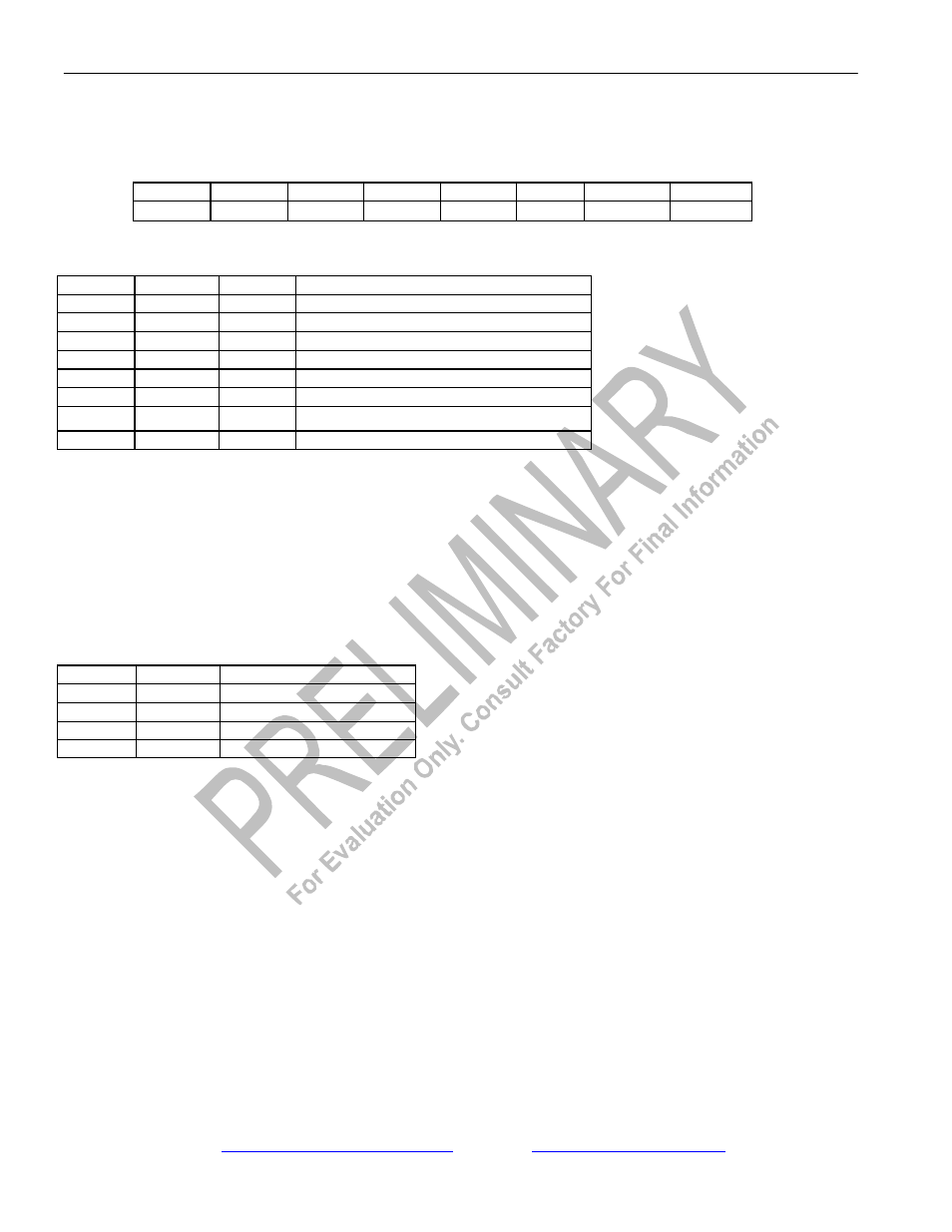
Register Name:
IBOC
Register Description:
Interleave Bus Operation Control Register
Register Address:
C5h
Bit #
7
6
5
4
3
2
1
0
Name
-
IBS1
IBS0
IBOSEL
IBOEN
DA2
DA1
DA0
Default
0
0
0
0
0
0
0
0
Bits 0 to 2/Device Assignment bits (DA0 to DA2).
DA2
DA1
DA0
DEVICE POSITION
0
0
0
1
st
Device on bus
0
0
1
2
nd
Device on bus
0
1
0
3
rd
Device on bus
0
1
1
4
th
Device on bus
1
0
0
5
th
Device on bus
1
0
1
6
th
Device on bus
1
1
0
7
th
Device on bus
1
1
1
8
th
Device on bus
Bit 3/Interleave Bus Operation Enable (IBOEN).
0 = Interleave Bus Operation disabled
1 = Interleave Bus Operation enabled
Bit 4/Interleave Bus Operation Select (IBOSEL). This bit selects channel- or frame-interleave mode.
0 = Channel Interleave
1 = Frame Interleave
Bits 5 to 6/IBO Bus Size bit 1 (IBS0 to IBS1). Indicates how many devices on the bus.
IBS1
IBS0
BUS SIZE
0
0
Two Devices on Bus
0
1
Four Devices on Bus
1
0
Eight Devices on Bus
1
1
Reserved for Future Use
Bit 7/Unused, must be set to zero for proper operation.