Maxim Integrated DS21Q55 User Manual
Page 116
Product Preview
DS21Q55
116 of 248
012103
Please contact
or search
http://www.maxim-ic.com
for updated
information.
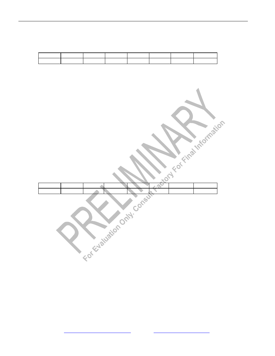
Register Name:
RFDL (RFDL register bit usage when BOCC.4 = 1)
Register Description:
Receive FDL Register
Register Address:
C0h
Bit #
7
6
5
4
3
2
1
0
Name
-
-
RBOC5
RBOC4
RBOC3
RBOC2
RBOC1
RBOC0
Default
0
0
0
0
0
0
0
0
Bit 0/BOC Bit 0 (RBOC0).
Bit 1/BOC Bit 1 (RBOC1).
Bit 2/BOC Bit 2 (RBOC2).
Bit 3/BOC Bit 3 (RBOC3).
Bit 4/BOC Bit 4 (RBOC4).
Bit 5/BOC Bit 5 (RBOC5).
Bit 6/This bit position is unused when BOCC.4 = 1.
Bit 7/This bit position is unused when BOCC.4 = 1.
Register Name:
SR8
Register Description:
Status Register 8
Register Address:
24h
Bit #
7
6
5
4
3
2
1
0
Name
-
-
BOCC
RFDLAD
RFDLF
TFDLE
RMTCH
RBOC
Default
0
0
0
0
0
0
0
0
Bit 0/Receive BOC Detector Change of State Event (RBOC). Set whenever the BOC detector sees a change of state to a
valid BOC. The setting of this bit prompts the user to read the RFDL register.
Bit 1/Receive FDL Match Event (RMTCH). Set whenever the contents of the RFDL register matches RFDLM1 or
RFDLM2.
Bit 2/TFDL Register Empty Event(TFDLE). Set when the transmit FDL buffer (TFDL) empties.
Bit 3/RFDL Register Full Event (RFDLF). Set when the receive FDL buffer (RFDL) fills to capacity.
Bit 4/RFDL Abort Detect Event (RFDLAD). Set when eight consecutive ones are received on the FDL.
Bit 5/BOC Clear Event (BOCC). Set when 30 FDL bits occur without an abort sequence.