Maxim Integrated DS21Q55 User Manual
Page 115
Product Preview
DS21Q55
115 of 248
012103
Please contact
or search
http://www.maxim-ic.com
for updated
information.
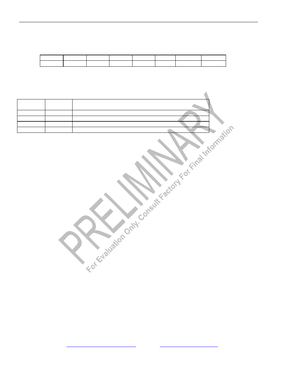
Register Name:
BOCC
Register Description:
BOC Control Register
Register Address:
37h
Bit #
7
6
5
4
3
2
1
0
Name
-
-
-
RBOCE
RBR
RBF1
RBF0
SBOC
Default
0
0
0
0
0
0
0
0
Bit 0/Send BOC (SBOC). Set = 1 to transmit the BOC code placed in bits 0 to 5 of the TFDL register.
Bits 1 to 2/Receive BOC Filter Bits (RBF0, RBF1). The BOC filter sets the number of consecutive patterns that must be
received without error prior to an indication of a valid message.
RBF1
RBF0
CONSECUTIVE BOC CODES FOR VALID SEQUENCE
IDENTIFICATION
0
0
None
0
1
3
1
0
5
1
1
7
Bit 3/Receive BOC Reset (RBR). A 0 to 1 transition will reset the BOC circuitry. Must be cleared and set again for a
subsequent reset.
Bit 4/Receive BOC Enable (RBOCE). Enables the receive BOC function. The RFDL register will report the received BOC
code.
0 = receive BOC function disabled
1 = receive BOC function enabled. The RFDL register will report BOC messages
Bit 5/Unused, must be set to zero for proper operation.
Bit 6/Unused, must be set to zero for proper operation.
Bit 7/Unused, must be set to zero for proper operation.