Maxim Integrated DS21Q55 User Manual
Page 159
Product Preview
DS21Q55
159 of 248
012103
Please contact
or search
http://www.maxim-ic.com
for updated
information.
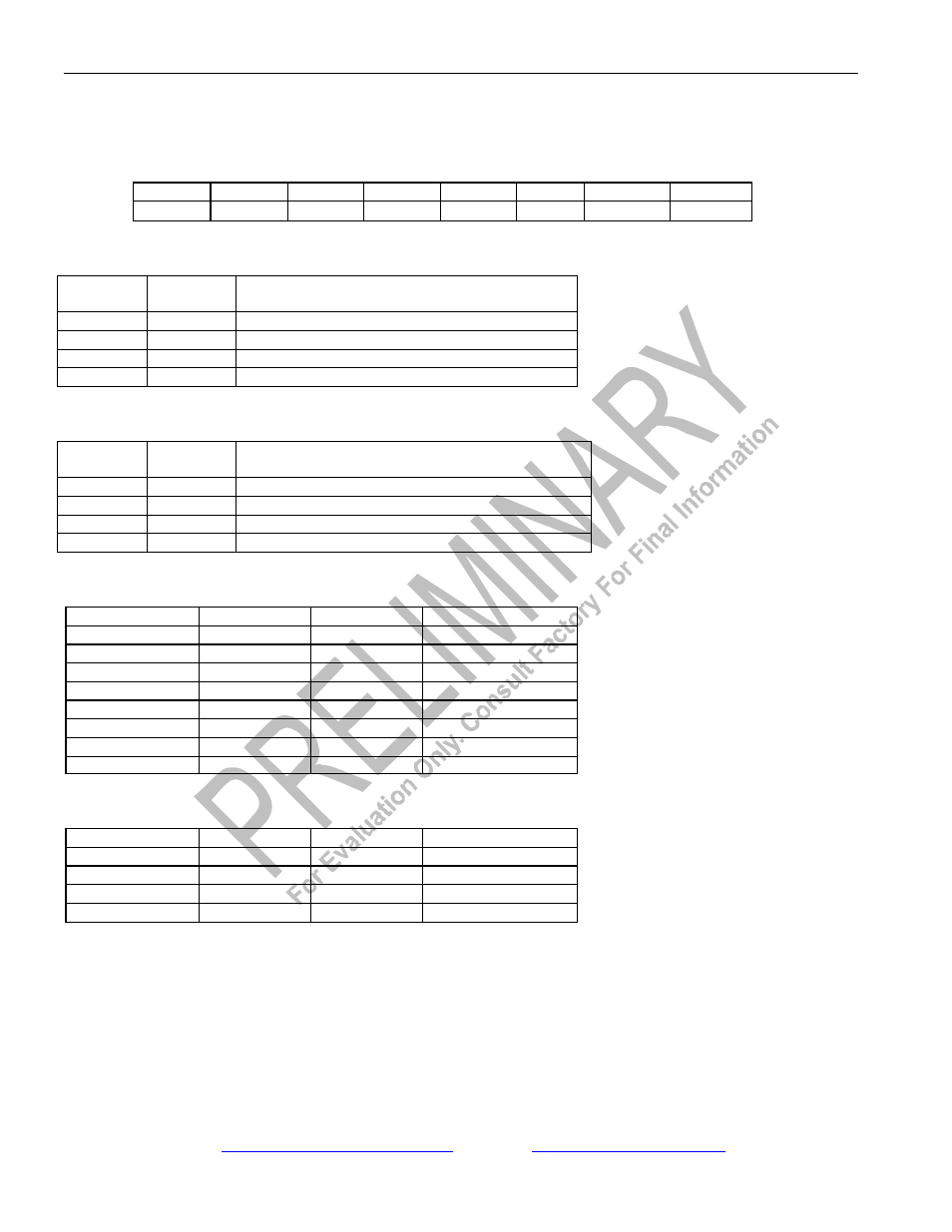
Register Name:
LIC4
Register Description:
Line Interface Control 4
Register Address:
7Bh
Bit #
7
6
5
4
3
2
1
0
Name
CMIE
CMII
MPS1
MPS0
TT1
TT0
RT1
RT0
Default
0
0
0
0
0
0
0
0
Bits 0 to 1/Receive Termination Select (RT0 to RT1).
RT1
RT0
INTERNAL RECEIVE TERMINATION
CONFIGURATION
0
0
Internal Receive-Side Termination Disabled
0
1
Internal Receive-Side 75O Enabled
1
0
Internal Receive-Side 100O Enabled
1
1
Internal Receive-Side 120O Enabled
Bits 2 to 3/Transmit Termination Select (TT0 to TT1).
TT1
TT0
INTERNAL TRANSMIT TERMINATION
CONFIGURATION
0
0
Internal Transmit-Side Termination Disabled
0
1
Internal Transmit-Side 75O Enabled
1
0
Internal Transmit-Side 100O Enabled
1
1
Internal Transmit-Side 120O Enabled
Bits 4 and 5/MCLK Prescaler for T1 Mode.
MCLK (MHz)
MPS1
MPS0
JAMUX (LIC2.3)
1.544
0
0
0
3.088
0
1
0
6.176
1
0
0
12.352
1
1
0
2.048
0
0
1
4.096
0
1
1
8.192
1
0
1
16.384
1
1
1
Bits 4 and 5/MCLK Prescaler for E1 Mode.
MCLK (MHz)
MPS1
MPS0
JAMUX (LIC2.3)
2.048
0
0
0
4.096
0
1
0
8.192
1
0
0
16.384
1
1
0
Bit 6/CMI Invert (CMII).
0 = CMI normal at TTIP and RTIP
1 = invert CMI signal at TTIP and RTIP
Bit 7/CMI Enable (CMIE).
0 = disable CMI mode
1 = enable CMI mode