Maxim Integrated DS21Q55 User Manual
Page 194
Product Preview
DS21Q55
194 of 248
012103
Please contact
or search
http://www.maxim-ic.com
for updated
information.
Register Name:
ESIBCR1
Register Description:
Extended System Information Bus Control Register 1
Register Address:
B0h
Bit #
7
6
5
4
3
2
1
0
Name
-
-
-
-
ESIBSEL2
ESIBSEL1
ESIBSEL0
ESIEN
Default
0
0
0
0
0
0
0
0
Bit 0/Extended System Information Bus Enable (ESIEN).
0 = disabled
1 = enabled
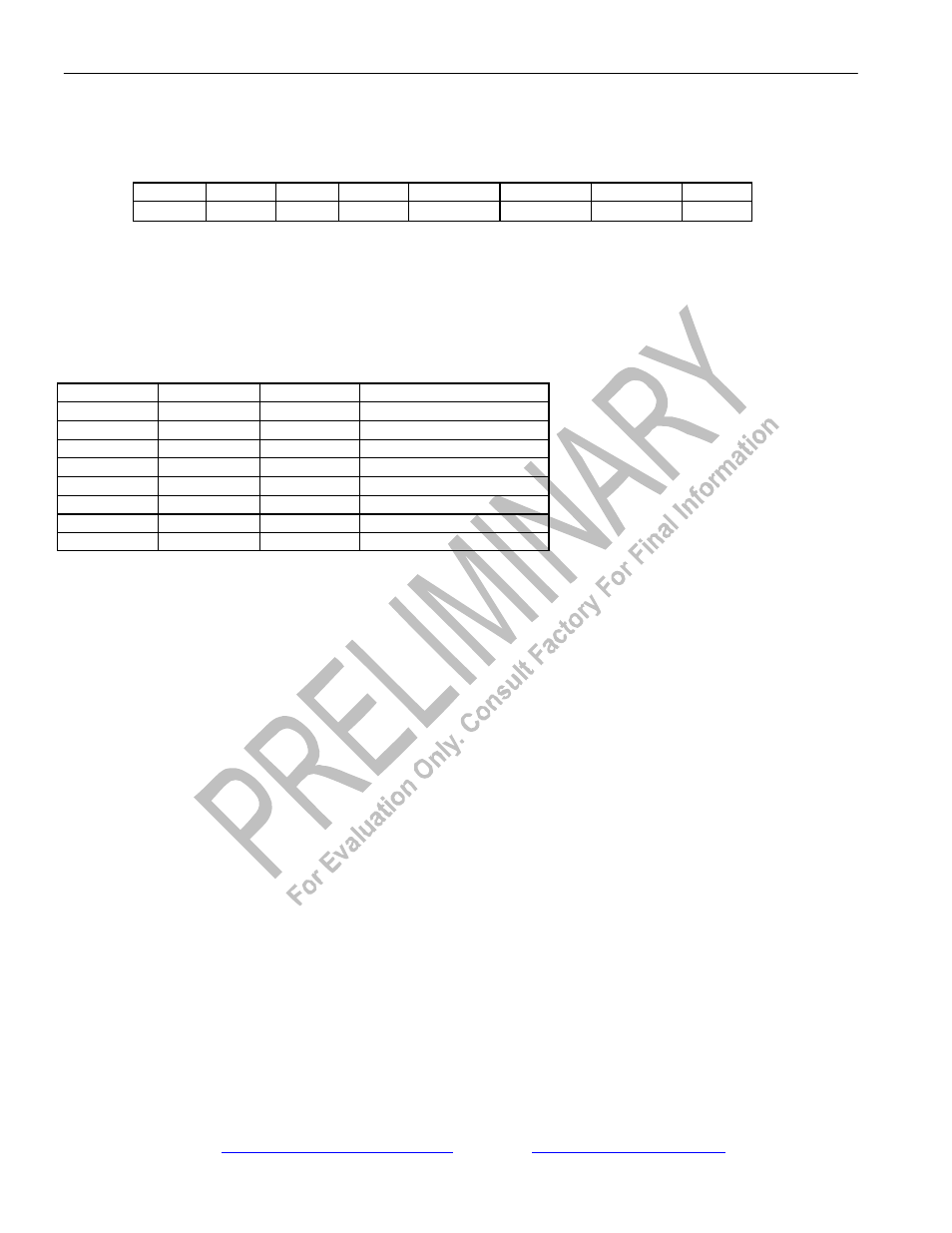
Bits 1 to 3/Output Data Bus Line Select (ESIBSEL0 to ESIBSEL2). These bits tell the device which data bus bit to output
the ESIB data on when one of the ESIB information registers is accessed. Each member of the ESIB group must have a unique
bit selected.
ESIBSEL2
ESIBSEL1
ESIBSEL0
BUS BIT DRIVEN
0
0
0
AD0
0
0
1
AD1
0
1
0
AD2
0
1
1
AD3
1
0
0
AD4
1
0
1
AD5
1
1
0
AD6
1
1
1
AD7
Bit 4/Unused, must be set to zero for proper operation.
Bit 5/Unused, must be set to zero for proper operation.
Bit 6/Unused, must be set to zero for proper operation.
Bit 7/Unused, must be set to zero for proper operation.