Maxim Integrated DS21Q55 User Manual
Page 175
Product Preview
DS21Q55
175 of 248
012103
Please contact
or search
http://www.maxim-ic.com
for updated
information.
Register Name:
RDNCD2
Register Description:
Receive -Down Code Definition Register 2
Register Address:
BCh
Bit #
7
6
5
4
3
2
1
0
Name
C7
C6
C5
C4
C3
C2
C1
C0
Default
0
0
0
0
0
0
0
0
Bit 0/Receive -Down Code Definition Bit 0 (C0). A “don’t care” if a 1 -bit to 7-bit length is selected.
Bit 1/Receive -Down Code Definition Bit 1 (C1). A “don’t care” if a 1 -bit to 7-bit length is selected.
Bit 2/Receive -Down Code Definition Bit 2 (C2). A “don’t care” if a 1-bit to 7-bit length is selected.
Bit 3/Receive -Down Code Definition Bit 3 (C3). A “don’t care” if a 1 -bit to 7-bit length is selected.
Bit 4/Receive -Down Code Definition Bit 4 (C4). A “don’t care” if a 1 -bit to 7-bit length is selected.
Bit 5/Receive -Down Code Definition Bit 5 (C5). A “don’t care” if a 1 -bit to 7-bit length is selected.
Bit 6/Receive -Down Code Definition Bit 6 (C6). A “don’t care” if a 1 -bit to 7-bit length is selected.
Bit 7/Receive -Down Code Definition Bit 7 (C7). A “don’t care” if a 1-bit to 7-bit length is selected.
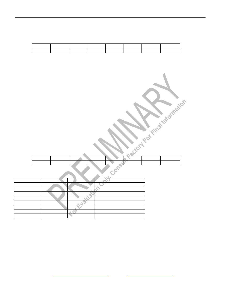
Register Name:
RSCC
Register Description:
In-Band Receive Spare Control Register
Register Address:
BDh
Bit #
7
6
5
4
3
2
1
0
Name
-
-
-
-
-
RSC2
RSC1
RSC0
Default
0
0
0
0
0
0
0
0
Bits 0 to 2/Receive Spare Code Length Definition Bits (RSC0 to RSC2).
RSC2
RSC1
RSC0
LENGTH SELECTED (Bits)
0
0
0
1
0
0
1
2
0
1
0
3
0
1
1
4
1
0
0
5
1
0
1
6
1
1
0
7
1
1
1
8/16
Bit 3/Unused, must be set to zero for proper operation.
Bit 4/Unused, must be set to zero for proper operation.
Bit 5/Unused, must be set to zero for proper operation.
Bit 6/Unused, must be set to zero for proper operation.
Bit 7/Unused, must be set to zero for proper operation.