IAI America CON-TG User Manual
Page 51
41
6.
Operation:
Mode
Flow
Chart
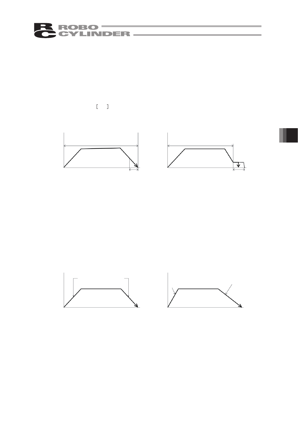
(6) Range: - Enter the positioning completion detection width in mm (distance to the target
position) in the positioning mode.
- The distance to the target position indicates that the value input here is the
upstream distance prior to reaching the target position and the position complete
signal is output when the actuator enters that upstream range.
The default value will depend on the actuator type. (see diagram A)
- Enter the maximum push amount (distance from the target position) in the push
mode.
mm
(see diagram B)
- When the push direction is a negative direction from the displayed coordinate,
a “negative” sign should be placed in the range column.
Diagram A
Diagram B
(7) Acc only MAX: - Selects either the assigned acceleration or the maximum acceleration.
Inputs are either 1 or 0. The default value is set as 0.
0: Assigned acceleration
The value placed in (4) will be used as the actual acceleration value
and deceleration value.
1: Maximum acceleration
This will automatically utilize the maximum acceleration matched to
the load.
Deceleration remains as the assigned value in (4).
Speed
Speed
(5) When push = 0
(2) Distance up to the position
(5) When push = other than 0
(2) Distance up to the position
Transfer distance
Transfer distance
(6) Positioning
width
(6) Positioning
width
Speed
Speed
(7) When Acc only MAX = 0
Transfer
distance
(7) When Acc only MAX = 1
Transfer
distance
The maximum acceleration
matches the load
(4) The value set in
Acc/Decl
(4) The value set in
Acc/Decl