3 description of each part – IAI America CON-TG User Manual
Page 25
15
4.
Functions
and
Specications
of
T
eaching
Pendant
4.3
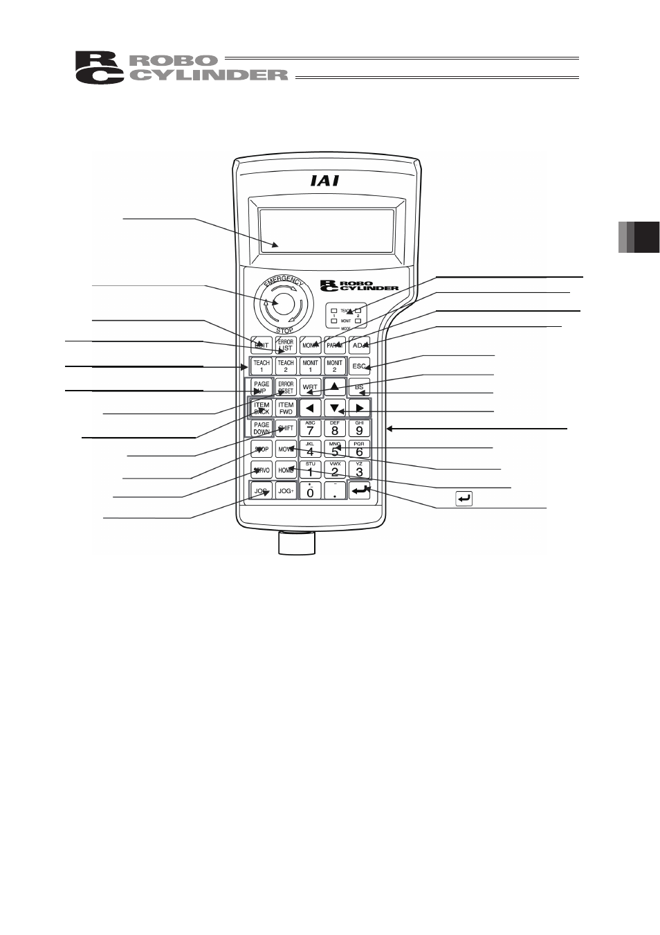
Description of Each Part
(1) LCD
This is a liquid crystal display with a maximum of horizontal: 20 characters per column and
vertical: 4 columns per row. The edit or teaching contents of various set values are displayed.
(2) EMERGENCY STOP (Emergency Stop Push Button Switch)
This switch is a mushroom-shaped push-lock, turn-reset type switch.
This switch connects serially with the controller emergency stop signal line. Once pushed down,
this switch will be in an emergency stop status and the power supply to the motor will be cut off
(normally, closed: b contact).
(* For information on the emergency stop signal line and its status, refer to the RC Robo
Cylinder Operating Manual.)
To reset the emergency stop status, turn the operating portion of this switch in the arrow direction.
(1) LCD
(23) Jog key
(4) EDIT mode select key
(10) ESC key
(11) PAGE UP/PAGE DOWN key
(15) ITEM BACK/FWD key
(2) EMERGENCY STOP
(3) TP operation mode display LED
(5) ERROR LIST mode select key
(6) MONITOR mode select key
(7) PARAMETER mode select key
(8) ADJUST mode select key
(9) TP operation mode select keys
(13) WRT key
(14) BS key
(16) Arrow keys
(18) Ten keys
(21) MOVE key
(22) HOME key
(24)
(Return) key
(12) ERROR RESET key
(17) SHIFT key
(19) STOP key
(20) SERVO key
(25) Dead-man Switch (CON-TG)