5 position data table contents – IAI America CON-TG User Manual
Page 43
33
6.
Operation:
Mode
Flow
Chart
6.5
Position Data Table Contents
6.5.1
Position Data Table Contents for PCON, ACON, SCON, ERC2
The setting items of the position data table are No., Position, Vel, Acc/Dcl, Push, LoTh, Range,
=RQH=RQH$FF'FO0RGH&PQG0RGHDQG6WRS0RGH7KH\DUHGLVSOD\HGLQVFUHHQV
7KHLWHPVRI=RQH=RQH$FF'FO0RGHDQG6WRS0RGHDUHHQDEOHG21RUGLVDEOHG2))
according to the controller type. (V1.00 and earlier)
For the version V1.10 or later, some items are changed and also added. These items are valid
only for SCON-CA, PCON-CA, ERC3 (CON Mode (CN)) and ERC3 PIO Converter.
(1) Gain Set “Cmnd Mode” is changed to “Gain Set”.
(2) Vibration Control Number “Vibration Control No.” is newly added.
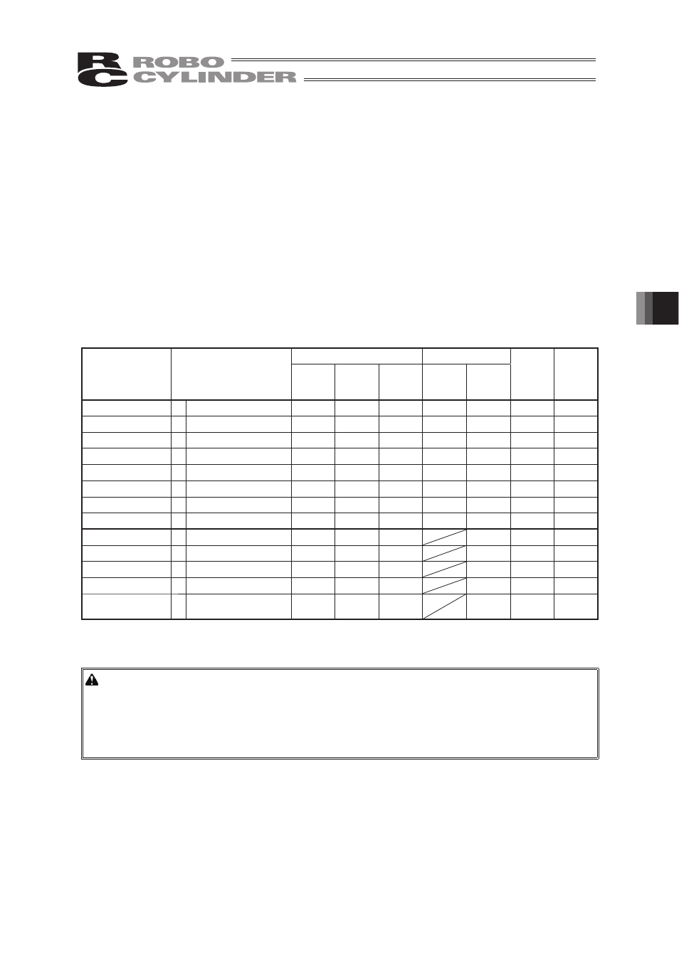
List of ON/OFF of Position Table According to Model
Position Table
=RQH
AccDcl Mode
Stop Mode
Gain Set
Vibration
Control
No.
Trapezoid S-shape
First-
order
Delay
Full Servo
Auto
Servo
OFF
ERC2
ż
PIO pattern: 3
ż
Ч
Ч
ż
ż
Ч
Ч
ERC2-SE
ż
-
ż
Ч
Ч
ż
Ч
Ч
Ч
ERC3
ż
PIO pattern: 2
ż
ż
ż
ż
ż
Ч
Ч
ERC3 PIO Converter
ż PIO pattern: 0, 1, 2, 4, 5
ż
ż
ż
ż
ż
Ч
Ч
PCON-C/CG/CF
ż PIO pattern: 0, 1, 2, 4, 5
ż
Ч
Ч
ż
ż
Ч
Ч
-CA
ż PIO pattern: 0, 1, 2, 4, 5
ż
ż
ż
ż
ż
Ч
Ч
-CY
ż
PIO pattern: 1
ż
Ч
Ч
ż
ż
Ч
Ч
-SE
ż
-
ż
Ч
Ч
ż
Ч
Ч
Ч
ACON-C/CG
ż PIO pattern: 0, 1, 2, 4, 5
ż
ż
ż
ż
Ч
Ч
-CY
ż
PIO pattern: 1
ż
ż
ż
ż
Ч
Ч
-SE
ż
-
ż
ż
ż
Ч
Ч
Ч
SCON-C positioner
ż PIO pattern: 0, 1, 2, 4, 5
ż
ż
ż
ż
Ч
Ч
SCON-CA positioner
ż
PIO pattern:
0, 1, 2, 4, 5, 6, 7
ż
ż
ż
ż
ż
ż
(1) No.
Indicates the position data number.
Warning:
Always specify absolute coordinates for the 3-point type of PCON-C/CG, PCON-CA,
ACON-C/CG, SCON-C, SCON-CA and ERC3 (CON Mode (CN)), and the proximity
switch type of PCON-CY and ACON-CY.
If you specify relative coordinates, a position data error will occur.
In the above case, if you specify “Push,” push completion cannot be judged.
(2) Position: Input the target position to move the actuator to, in [mm].
- Absolute Coordinates: Input the target location by determining the distance between
the original point and target position. No negative value can
be input.
- Relative Coordinates: Input the target location by determining the distance between
the current position and target position. Any negative value
can be input (if coordinates are in the negative direction).