2 controller selection (when using multiple units) – IAI America CON-TG User Manual
Page 37
27
6.
Operation:
Mode
Flow
Chart
6.2
Controller Selection (when using multiple units)
In the case of multiple units connected serially via the communication line, the axis
selection screen will be displayed. For a single unit, since there is no need to
select the axis, the first screen below will not appear (refer to Section 6.3 entitled
If the jig No. is incremented or decremented with the
or
key, power-on
controllers will be displayed in order when the power is applied to the Teaching
Pendant. Display the controller to be selected.
Then, press the return key. The selection will be confirmed and the screen will
change to the “Mode Select” screen.
The controller can connect up to 16 units. However, the PCON, ACON or SCON
group controllers cannot be used by linking to the RCP, RCS, E-Con or RCP2 controllers.
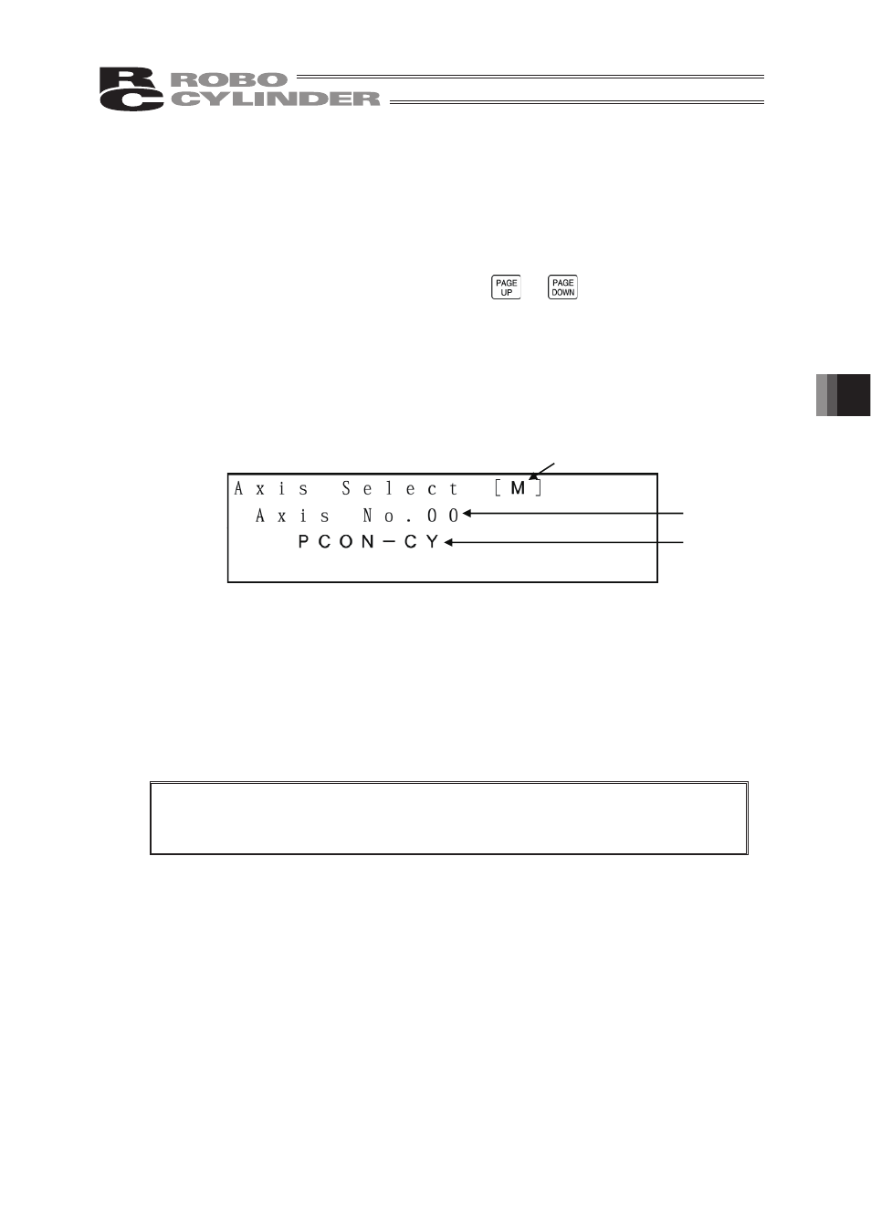
Axis Selection Screen
(1) Protocol type display
M: Modbus, T: proprietary protocol
(2) Axis No. display
(3) Connection axis display: In the case of PCON, ACON or SCON, the series name and type
name of the connection axis such as PCON-CY will be displayed.
In the case of RCP, RCS, E-Con or RCP2, “Connected” will be
Caution: In the case of controllers with the PORT switch, only the powered controller(s)
will be detected when the PORT switch is ON and power is present for the
The content explained hereinafter will be based on operation in response to the selected
axis (controller).
(3)
(1)
(2)
Operational Mode Selection of this manual).
displayed.
Teaching Pendant.