Fru:lcd, Removing the system unit lcd, Unplug the lcd’s connector as shown in figure 4-60 – HP B1000 User Manual
Page 145: Figure460. removing the system unit lcd, Replacing the, Plug in the lcd connector as shown in figure 4-60, System unit lcd, Figure 4-60.. removing the system unit lcd
Chapter 4
145
Field Replaceable Units
FRU Removal and Replacement
System Unit LCD
This section describes how to remove and replace the B1000/C3000 workstation power
switch/LCD assembly, which is located on the front panel.
Removing the System Unit LCD
To remove the LCD assembly, perform the following steps:
1. Open the system unit’s front panel as shown in the section “Opening the System Unit
Front Panel.”
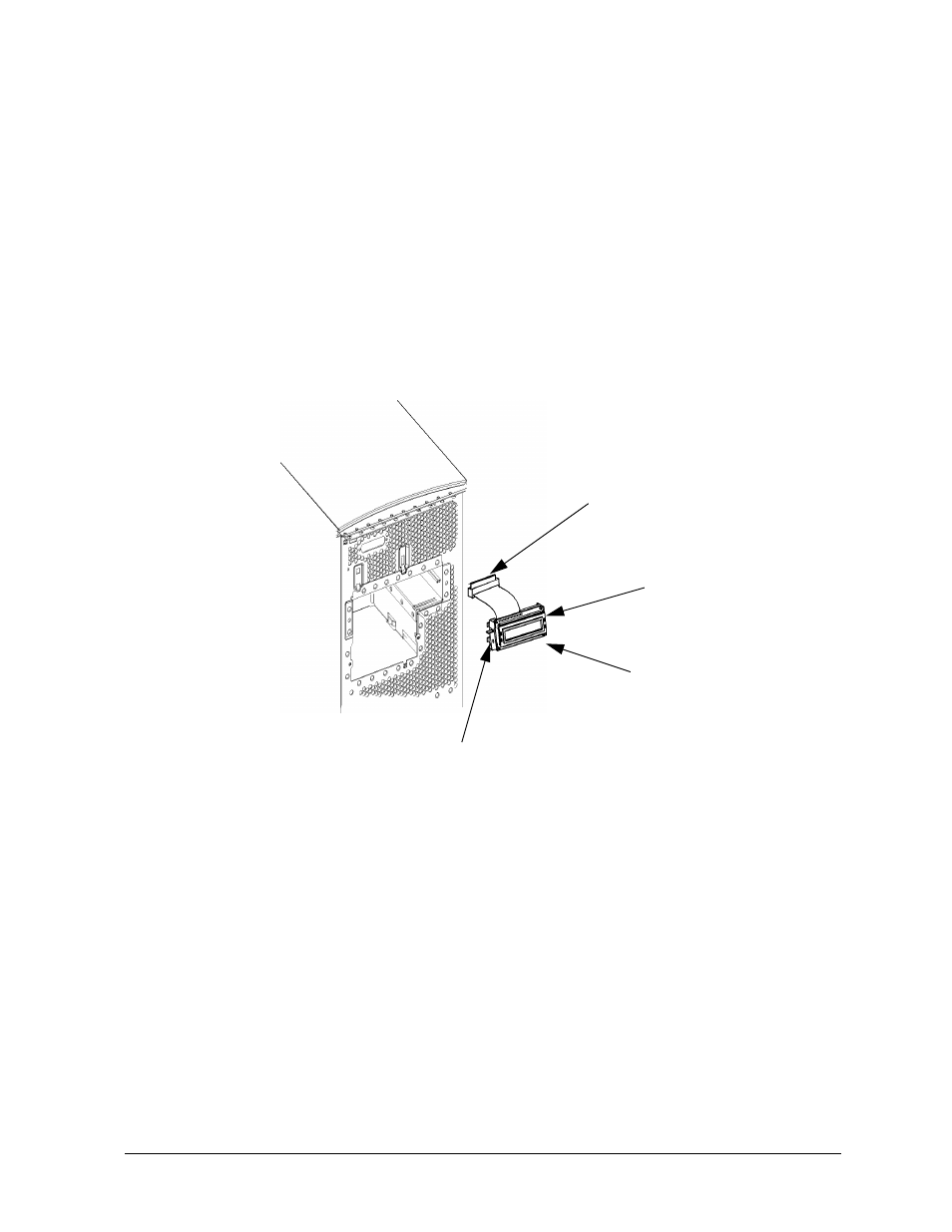
2. Unplug the LCD’s connector as shown in Figure 4-60.
Figure 4-60. Removing the System Unit LCD
3. Press inward on the mount clip located on the right side of the LCD mount and pull the
right side of the LCD outward in a clockwise motion. See Figure 4-60.. This action
releases the LCD’s left side mounting clips.
Replacing the Power Switch/LCD Assembly
To replace the power switch/LCD assembly, do the following:
1. Open the system unit’s front panel as shown in the section “Opening the System Unit
Front Panel.”
2. Insert the LCD’s left-side mounting clips into the slots shown on the system unit
chassis. See Figure 4-60. Press inward on the mount clip located on the right side of the
LCD mount bracket and insert this clip into the hole provided for it on the system unit
chassis.
3. Plug in the LCD connector as shown in Figure 4-60.
LCD Connector
LCD
Mount Clip
Mounting Clips