Figure48. propping up the power supply, Closing the system, Tighten both captive screws in place as seen in – HP B1000 User Manual
Page 103: Removing the power supply, To remove the power supply follow these steps, Figure 4-8.. propping up the power supply
Chapter 4
103
Field Replaceable Units
FRU Removal and Replacement
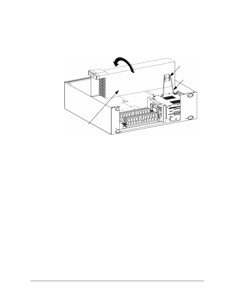
the power supply is propped in the upright position as shown in Figure 4-8. Note that
the bail automatically springs into the bail lock to secure the power supply.
Figure 4-8. Propping Up the Power Supply
Closing the System
Once you have completed the task you set out to perform, you are ready to close the
system. To close the system follow these steps:
1. Push slightly back on the power supply until you are able to remove the bail from the
bail lock. Using the power supply handle lower it downward into its original operating
position. See Figure Figure 4-7.
2. Tighten both captive screws in place as seen in Figure 4-7.
3. Replace the left side panel of the system unit as shown in the section “Closing the Left
Side Panel of the System Unit” in this chapter.
Removing the Power Supply
To remove the power supply follow these steps:
1. Follow the steps covered in the section “Propping Up the Power Supply.”
2. Disconnect both power cables from the system board, the control cable, and the power
cable for the SCA disk drives. See Figure 4-9. Note that these cables are keyed to
prevent you from incorrectly plugging them in when you replace the power supply.
Bail
Bail Lock
Bail
Power Supply