Cycle parameters – HEIDENHAIN TNC 320 (34055x-06) Cycle programming User Manual
Page 95
TAPPING WITH CHIP BREAKING (Cycle 209, DIN/ISO: G209)
4.4
4
TNC 320 | User's Manual Cycle Programming | 5/2013
95
Cycle parameters
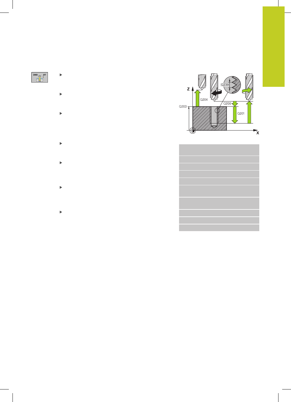
Set-up clearance Q200 (incremental): Distance
between tool tip and workpiece surface. Input range
0 to 99999.9999
Thread depth Q201 (incremental): Distance
between workpiece surface and root of thread.
Input range -99999.9999 to 99999.9999
Thread pitch Q239: Pitch of the thread. The
algebraic sign differentiates between right-hand and
left-hand threads:
+
= right-hand thread
–
= left-hand thread Input range -99.9999 to 99.9999
Coordinate of workpiece surface Q203 (absolute):
Coordinate of the workpiece surface. Input range
-99999.9999 to 99999.9999
2nd set-up clearance Q204 (incremental):
Coordinate in the spindle axis at which no collision
between tool and workpiece (fixtures) can occur.
Input range 0 to 99999.9999
Infeed depth for chip breaking Q257
(incremental): Depth at which the TNC carries out
chip breaking. No chip breaking if 0 is entered. Input
range 0 to 99999.9999
Retraction rate for chip breaking Q256: The
TNC multiplies the pitch Q239 by the programmed
value and retracts the tool by the calculated value
during chip breaking. If you enter Q256 = 0, the
TNC retracts the tool completely from the hole (to
the set-up clearance) for chip breaking. Input range
0.1000 to 99999.9999
NC blocks
26 CYCL DEF 209 TAPPING W/ CHIP
BRKG
Q200=2
;SET-UP CLEARANCE
Q201=-20
;DEPTH
Q239=+1
;THREAD PITCH
Q203=+25
;SURFACE COORDINATE
Q204=50
;2ND SET-UP
CLEARANCE
Q257=5
;DEPTH FOR CHIP
BRKNG
Q256=+25
;DIST. FOR CHIP BRKNG
Q336=50
;ANGLE OF SPINDLE
Q403=1.5
;RPM FACTOR