13 measure plane (cycle 431, din/iso: g431), Cycle run, Please note while programming – HEIDENHAIN TNC 320 (34055x-06) Cycle programming User Manual
Page 363: Measure plane (cycle 431, din/iso: g431)
MEASURE PLANE (Cycle 431, DIN/ISO: G431) 16.13
16
TNC 320 | User's Manual Cycle Programming | 5/2013
363
16.13
MEASURE PLANE (Cycle 431, DIN/ISO:
G431)
Cycle run
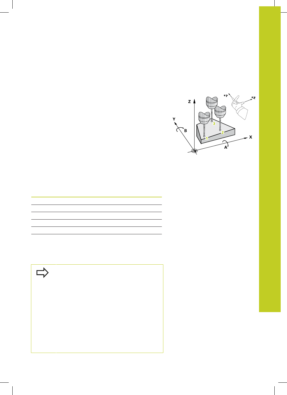
Touch Probe Cycle 431 finds the angle of a plane by measuring
three points. It saves the measured values in system parameters.
1 Following the positioning logic (See "Executing touch probe
cycles", page 259), the TNC positions the touch probe at rapid
traverse (value from
FMAX column) to the programmed starting
point
1
and measures the first touch point of the plane. The TNC
offsets the touch probe by the safety clearance in the direction
opposite to the direction of probing.
2 The touch probe returns to the clearance height and then moves
in the working plane to starting point
2
and measures the actual
value of the second touch point of the plane.
3 The touch probe returns to the clearance height and then moves
in the working plane to starting point
3
and measures the actual
value of the third touch point of the plane.
4 Finally the TNC returns the touch probe to the clearance
height and saves the measured angle values in the following Q
parameters:
Parameter number
Meaning
Q158
Projection angle of the A axis
Q159
Projection angle of the B axis
Q170
Spatial angle A
Q171
Spatial angle B
Q172
Spatial angle C
Q173 to Q175
Measured values in the touch probe
axis (first to third measurement)
Please note while programming:
Before a cycle definition you must have programmed
a tool call to define the touch probe axis.
For the TNC to be able to calculate the angular
values, the three measuring points must not be
positioned on one straight line.
The spatial angles that are needed for tilting the
working plane are saved in parameters Q170 – Q172.
With the first two measuring points you also specify
the direction of the reference axis when tilting the
working plane.
The third measuring point determines the direction
of the tool axis. Define the third measuring point in
the direction of the positive Y axis to ensure that the
position of the tool axis in a clockwise coordinate
system is correct.