Circle and circular arcs, Yx z dr– dr+ y x z – HEIDENHAIN TNC 360 User Manual User Manual
Page 98
TNC 360
5-14
5
Programming Tool Movements
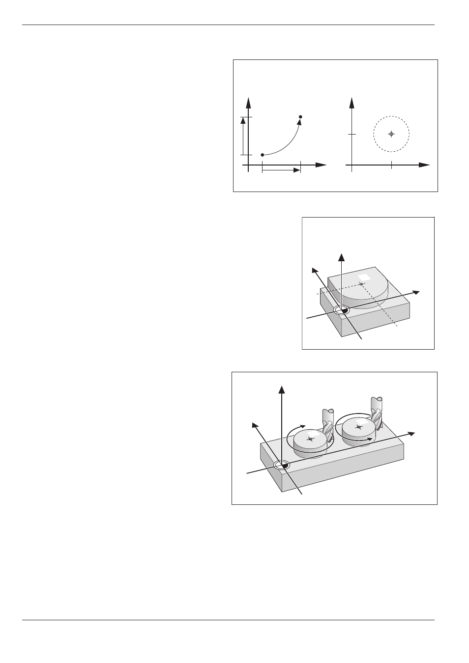
Fig. 5-17:
Circular arc and circle center
Fig. 5.18:
Circle center coordinates
Fig. 5.19:
Direction of rotation for circular movements
5.4
Path Contours – Cartesian Coordinates
CC
CC
Y
X
Z
DR–
DR+
Y
X
Z
Y
CC
CC
X
CC
Y
X
Y
X
Y
CC
CC
X
CC
Circle and circular arcs
The TNC can control two machine axes simultane-
ously to move the tool in a circular path.
Circle Center CC
You can define a circular movement by entering its
center CC.
A circle center can also serve as reference (pole) for
polar coordinates.
Direction of Rotation DR
When there is no tangential transition to another
contour element, enter the mathematical direction
of rotation DR, where
• a clockwise direction of rotation is mathematical-
ly negative: DR-
• a counterclockwise direction of rotation is
mathematically positive: DR+
- TNC 122 User Manual (63 pages)
- TNC 122 Technical Manual (70 pages)
- TNC 360 Service Manual (157 pages)
- TNC 416 Technical Manual (510 pages)
- TNC 335 Technical Manual (581 pages)
- TNC 360 ISO-Programmierung (2 pages)
- TNC 415 (280 540) User Manual (227 pages)
- TNC 370D (92 pages)
- TNC 416 (289 pages)
- TNC 415 (280 540) Technical Manual (752 pages)
- TNC 415 (259 96x) Service Manual (195 pages)
- TNC 407 (280 580) User Manual (376 pages)
- iTNC 530 (340 420) Pilot (104 pages)
- TNC 407 (280 580) ISO Programming (333 pages)
- TNC 415 (280 540) Service Manual (252 pages)
- PT 880 Installation (112 pages)
- ND 100 User Manual (116 pages)
- ND 287 User Manual (147 pages)
- ND 280 Quick Start (12 pages)
- ND 200 (156 pages)
- ND 282 (10 pages)
- ND 287 Quick Start (26 pages)
- ND 282 B (39 pages)
- ND 281 A (44 pages)
- ND 281 B v.1 (53 pages)
- ND 281 B v.2 (65 pages)
- ND 221 v.2 (10 pages)
- ND 231 B v.2 (56 pages)
- ND 231 B v.1 (44 pages)
- ND 221 B v.2 (45 pages)
- ND 550 v.2 (8 pages)
- NDP 560 (10 pages)
- ND 523 (93 pages)
- ND 570 (8 pages)
- ND 750 v.2 (46 pages)
- ND 760 v.3 (72 pages)
- ND 770 v.1 (40 pages)
- ND 770 v.3 (41 pages)
- ND 760 E (44 pages)
- IOB 49 (21 pages)
- NDP 960 (68 pages)
- ND 780 Installation (132 pages)
- ND 970 (47 pages)
- ND 1100 Quick Start (36 pages)