Contour geometry (cycle 14) – HEIDENHAIN TNC 360 User Manual User Manual
Page 170
8-17
TNC 360
8
Cycles
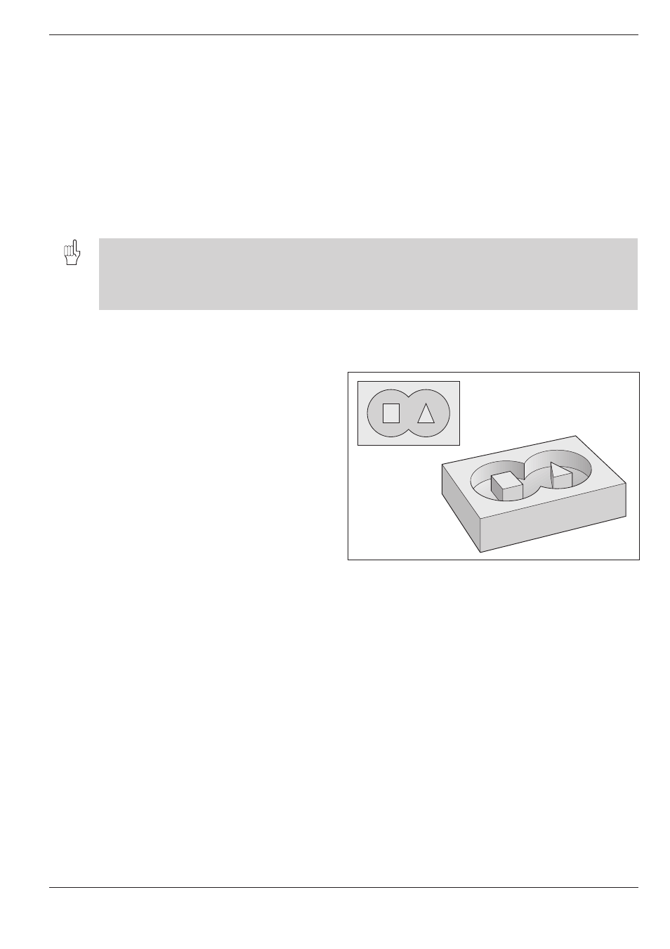
Fig. 8.13:
Example of an SL contour: A, B = pockets; C, D = islands
8.3
SL Cycles
A
B
D
C
The machining data are defined in the following cycles:
• PILOT DRILLING (cycle 15)
• ROUGH-OUT (cycle 6)
• CONTOUR MILLING (cycle 16)
Each subprogram defines whether RL or RR radius compensation applies.
The sequence of points determines the direction of rotation in which the
contour is to be machined. The control deduces from these data whether
the specific subprogram describes a pocket or an island:
• For a pocket the tool path is inside the contour
• For an island the tool path is outside the contour
• The way the SL contour is machined is determined by MP7420.
• We recommend a graphical test run before you machine the part. This will show if all contours were correctly
defined.
• All coordinate transformations are allowed in the subprograms for the subcontours.
• F and M words are ignored in the subprograms for the subcontours.
The following examples will at first use only the ROUGH-OUT cycle.
Later, as the examples become more complex, the full range of possibili-
ties of this group of cycles will be illustrated.
CONTOUR GEOMETRY (Cycle 14)
Application
Cycle 14 CONTOUR GEOMETRY contains the list
of subcontours that make up the complete contour
Input data
Enter the LABEL numbers of the subprograms. A
maximum of 12 subprograms can be listed.
Effect
Cycle 14 becomes effective as soon as it is defined.