The operating panel, The screen – HEIDENHAIN TNC 360 User Manual User Manual
Page 21
TNC 360
1-3
1
Introduction
.
0
1
2
3
4
5
6
7
8
9
+/
Z
Y
X
CE
C
CC
CT
CR
IV
RND
PGM
CALL
PGM
NR
CL
PGM
L
MOD
BLK
FORM
MAGN
START
Q
DEF
P
MOD
END
Q
0
50
100
150
0
50
100
150
S %
F %
GRAPHICS
R
+
R
R-
L
TOOL
CALL
TOOL
DEF
NO
ENT
CYCL
CALL
CYCL
DEF
STOP
LBL
CALL
LBL
SET
GOTO
EXT
TOUCH
PROBE
DEL
ENT
HEIDENHAIN
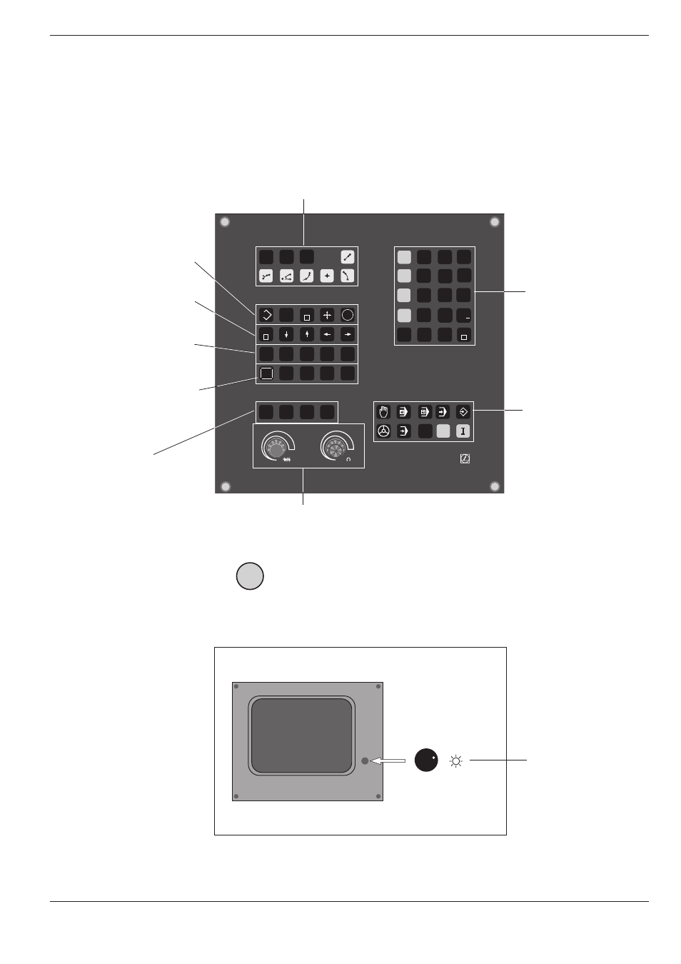
The Operating Panel
The keys on the TNC operating panel are identified with easy-to-
remember abbreviations and symbols. The keys are grouped accord-
ing to function:
• Program selection
• Path function keys
• Numerical entries
• Axis selection
• Q parameter
programming
• Operating modes
• Incremental and
polar coordinates
1.1
The TNC 360
• External data transfer
• Probing functions
• Editing functions
• GOTO statement
• Arrow keys
• STOP key
• Programming of cycles,
program section repeats
and subprograms
• NO ENT key
• Tool-related entries
Override controls
for spindle speed
and feed rate
The functions of the individual keys are de-
scribed on the inside front cover.
Graphic operating
modes
The machine operating buttons, such as for NC start, are described in the manual for your machine tool.
In this manual they are shown in gray.
The Screen
Brightness control
(BE 212 only)
Header
The header of the screen shows the selected operating mode. Dialog
questions and TNC messages also appear there.
I