Powermax – Hypertherm Powermax105 Service Manual User Manual
Page 283
Power SuPPly ComPonent rePlaCement
powermax
105 Service Manual
9-85
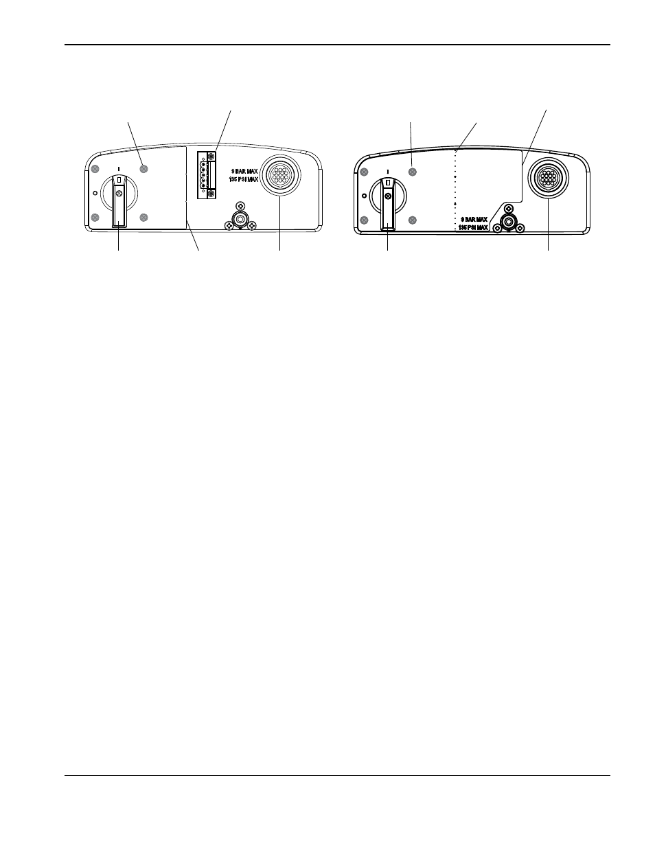
RS485 connector installed
RS485 connector not installed
Label
perforation
Power switch screws (4)
(behind label)
Power switch screws (4)
(behind label)
Optional RS485
connector
Optional CNC
interface connector
Optional CNC
interface connector
Right edge
of label
Power switch
handle
Power switch
handle
Right edge
of label
12. Remove the handle screw that secures the power switch handle to the post.
13. Pull the power switch handle straight off the post.
14. Pry up the right edge of the power switch label. If the optional RS485 connector is not installed, the label extends
to the right side of the inlet gas fitting.
15. Peel off the entire label to expose the four mounting screws that secure the power switch to the rear end panel.
16. Disengage the power switch from the rear end panel by removing the four mounting screws.
17. Remove the rear end panel.
18. Align the mounting holes in the new rear end panel with the corresponding holes in the power switch.
19. Secure the power switch to the rear end panel by tightening the four mounting screws to 17.3 kg cm (15 in.-lbs).
20. If the RS485 connector is installed, bend and tear the new label at the perforation.
21. Peel the backing off the new label and affix to the rear end panel, being careful to align the hole in the label with the
corresponding hole in the rear end panel.
22. Push the power switch handle straight onto the post and tighten the handle screw to 11.5 kg cm (10 in.-lbs).
23. If removed in an earlier step, secure the RS485 connector to the rear end panel by tightening the two mounting
screws to 11.5 kg cm (10 in.-lbs).