Powermax – Hypertherm Powermax105 Service Manual User Manual
Page 269
Power SuPPly ComPonent rePlaCement
powermax
105 Service Manual
9-71
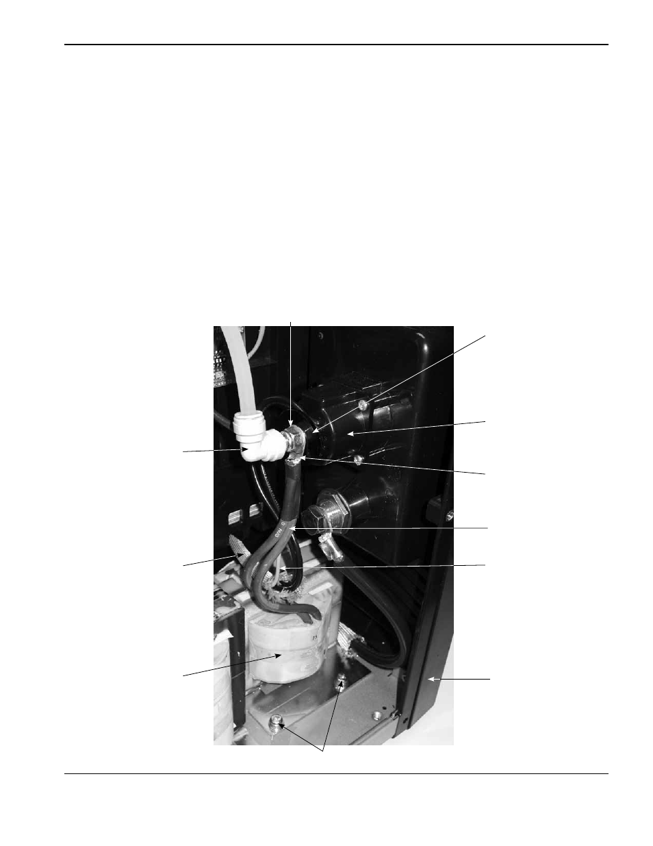
4. Disconnect the 90° push-to-connect fitting by pushing in the plastic ring (closest to the brass nut) and pulling the
fitting away from the nut.
5. Disconnect the electrode wire and short inductor wires by removing the brass nut that secures the ring terminal to
the quick disconnect housing.
Note: The electrode wire and short inductor wires are captured in the same wire connector.
6. Pull the electrode wire through the protective sheathing that passes through the center panel.
7. Carefully slide the front end panel a short distance away from the base of the power supply.
8. Remove the two mounting screws in the base of the output inductor.
Ring terminal
Electrode wire
Protective sheathing
Front end panel
90° push-to-connect
fitting
Brass nut
Output inductor
Mounting screws
Short inductor wires (2)
Quick disconnect housing
Plastic washer