Powermax – Hypertherm Powermax105 Service Manual User Manual
Page 270
Power SuPPly ComPonent rePlaCement
9-72
powermax
105 Service Manual
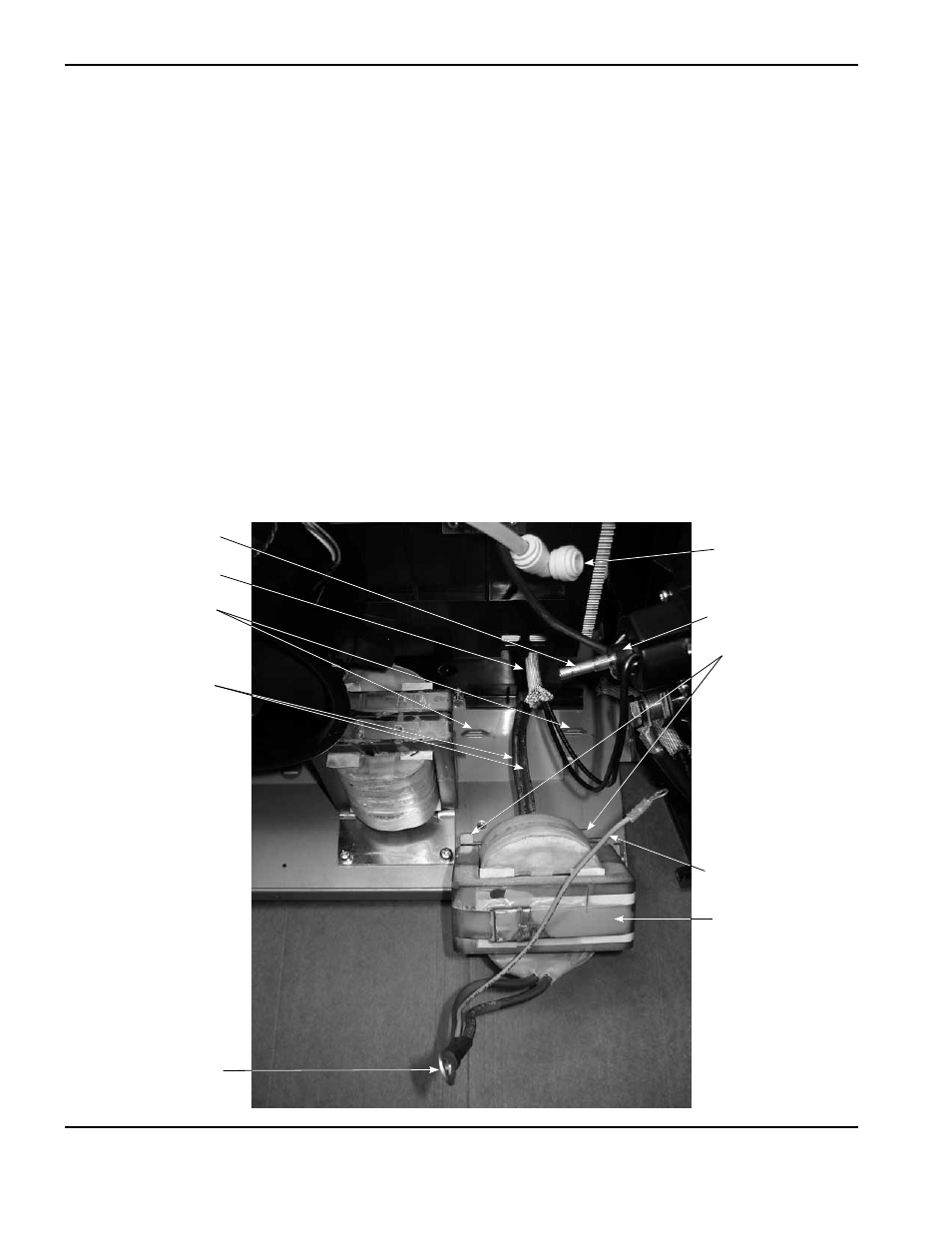
9. Lift the output inductor out of the power supply while guiding the long inductor wires through the opening in the
bottom of the center panel.
10. Place the new output inductor in the power supply while guiding the long inductor wires through the opening in the
bottom of the center panel.
11. Insert the tabs on the front of the output inductor in the slots in the base of the power supply.
12. Push the electrode wire through the protective sheathing that passes through the center panel.
13. Tighten the two supplied mounting screws in the base of the output inductor to 69.1 kg cm (60 in.-lbs).
14. Verify that the plastic washer is installed over the plastic hub on the rear of the quick disconnect receptacle.
15. Place the ring terminal over the brass fitting and tighten the nut onto the brass fitting. Tighten the nut to
46.1 kg cm (40 in.-lbs).
16. Push the 90° push-to-connect fitting onto the brass fitting until full seated.
Tabs
Long inductor wires
Slots in base
Electrode wire
Plastic hub
Ring terminal
Protective sheathing
Brass fitting
90° push-to-connect
fitting
Output inductor