Replace the output inductor, Powermax, Power supply component replacement 9-70 – Hypertherm Powermax105 Service Manual User Manual
Page 268: 105 service manual, Front end panel mounting screws
Power SuPPly ComPonent rePlaCement
9-70
powermax
105 Service Manual
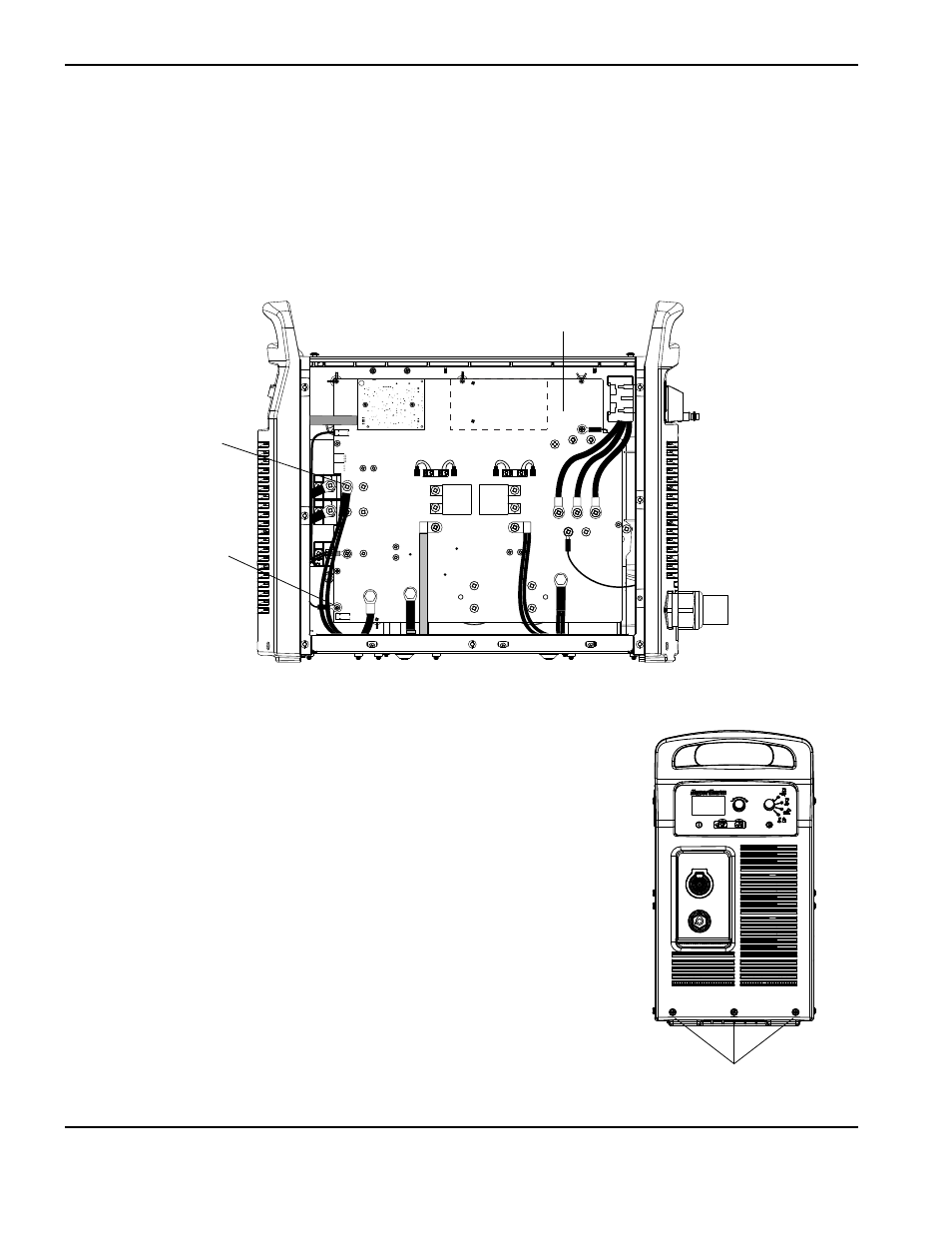
Replace the output inductor
1. Remove the screw at J28 that secures the electrode wire to the power board.
2. Remove the screw securing the output inductor wires to the power board.
Note: The power board shown below is a 200-600 V CSA model. The connections for the output inductor
wires and the electrode wire are the same for all models.
Front end panel
mounting screws
3. Remove the three mounting screws from the bottom of the front end panel.
J22
J21
J20
J19
J27
WORK
LEAD
J26
J25
+
_
+
_
RED
J18
ORG
J17
J32
J11
B
R
J28
TP7
TP9
TP8
W
R
B
Output inductor wires
mounting screw
Electrode wire
mounting screw
Power board
This manual is related to the following products: